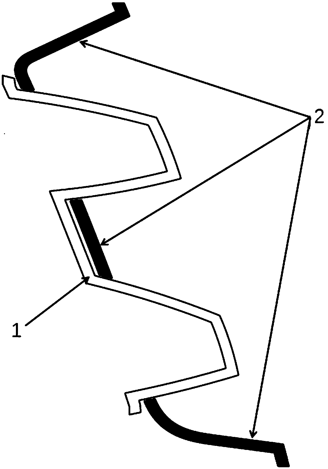
Optical element for vehicle light, vehicle light and vehicle

A technology of optical parts and lights, applied in the direction of headlights, optical signals, vehicle parts, etc., to reduce management and stocking costs

Pending Publication Date: 2019-01-25
HASCO VISION TECHNOLOGY CO LTD
View PDF0 Cites 0 Cited by
  • Summary
  • Abstract
  • Description
  • Claims
  • Application Information

AI Technical Summary

Benefits of technology

This technology allows for precise control over how much scattered coating or other substances should appear on surfaces like windows during manufacturing processes while minimizing costs associated with preparation and storage.

Problems solved by technology

This patented technical problem addressed by this patents relates to improving the performance of vehicle lights without adding extra components like scattered reflectors for better control over their luminous intensity levels.

Method used


Image

  • Optical element for vehicle light, vehicle light and vehicle

Examples


Embodiment Construction

[0016] Various embodiments of the invention will be described with reference to the accompanying drawings. In the description and drawings, elements with similar structures or functions will be denoted by the same symbol. It can be understood that the drawings are only used for reference and description, and are not intended to limit the present invention. The dimensions shown in the drawings are only for the convenience of clear description, and do not limit the proportional relationship or give an exhaustive description of the present invention, nor limit the scope of the present invention.

[0017] In describing the present invention, it is to be understood that the terms "upper", "lower", "front", "rear", "left", "right", "vertical", "horizontal", "top", The orientation or positional relationship indicated by "bottom", "inner", "outer", etc. is based on the orientation or positional relationship shown in the drawings, and is only for the convenience of describing the present


PUM


Abstract

The invention relates to an optical element for a vehicle light, the vehicle light and a vehicle, and belongs to the field of vehicle light products. The optical element for the vehicle light comprises a transparent part and a non-transparent part, ad the surface of the transparent part is spray-coated with scattering coating. The vehicle light comprises the optical element for the vehicle light.The vehicle comprises the vehicle light. Accordingly, the method of spray-coating the scattering coating replaces the method of directly adding scattering particles in transparent base materials, so that only few types of scattering coating and diluent which have the benchmark concentration need to be prepared; the concentration of the scattering coating is adjusted according to production needs so that all transmittance requirements of different products can be met, and the management and stock cost is lowered.

Description


Claims


Application Information

Patent Timeline
Owner HASCO VISION TECHNOLOGY CO LTD
Why Eureka
Try Eureka