LDW function detection method

A technology for function detection and test scenarios, applied in the field of intelligent transportation, to shorten the research and development cycle and avoid dangerous driving

Pending Publication Date: 2019-03-08
ANHUI JIANGHUAI AUTOMOBILE GRP CORP LTD
View PDF3 Cites 3 Cited by
  • Summary
  • Abstract
  • Description
  • Claims
  • Application Information

AI Technical Summary

Benefits of technology

This technology helps detect lamps better during severe work environments like rain or snow without causing dangerously high risk for drivers due to their poor visibility at nighttime when they cannot see clearly through fogged windows caused by heavy precipitation. It also allows vehicles with cameras to monitor road surfaces more effectively while navigating around them accurately.

Problems solved by technology

Technics: The technical problem addressed in this patented technology relating to improving automobile safety systems involves developing better ways to predict if there will occur any sudden changes on how well they behave under different scenarios (such as rain/ice) without actually stopping them down completely due to their lack of ability to react properly with surrounding obstacles like cars).

Method used


Image

  • LDW function detection method

Examples


Embodiment Construction

[0022] Embodiments of the present invention are described in detail below, examples of which are shown in the drawings, wherein the same or similar reference numerals designate the same or similar elements or elements having the same or similar functions throughout. The embodiments described below by referring to the figures are exemplary only for explaining the present invention and should not be construed as limiting the present invention.

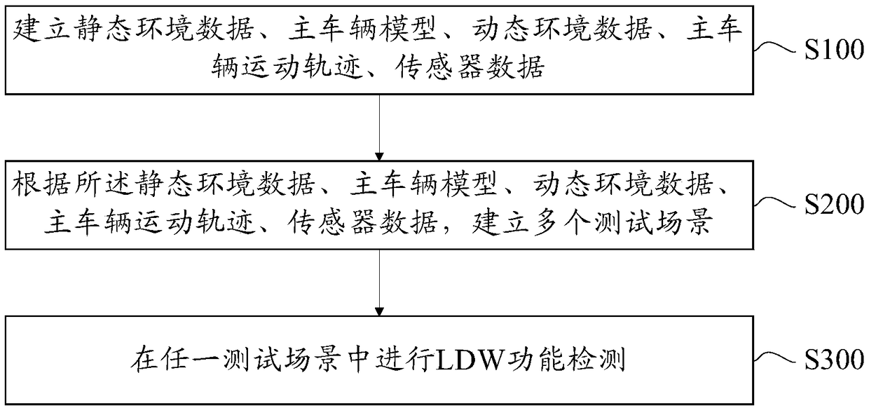
[0023] Such as figure 1 As shown, the embodiment of the present invention provides a LDW function detection method, including:

[0024] S100, establishing static environment data, host vehicle model, dynamic environment data, host vehicle movement trajectory, and sensor data.

[0025] Wherein, the static environment data includes road data, weather data, tree data, house data and traffic sign signal data. Among them, the establishment of road data needs to set the number of lanes, lane lines, marking lines, fences, etc. according to the a


PUM


Abstract

The invention discloses an LDW function detection method. The method comprises the steps of establishing the static environment data, a main vehicle model, the dynamic environment data, a main vehiclemotion track and the sensor data; establishing a plurality of test scenes according to the static environment data, the main vehicle model, the dynamic environment data, the main vehicle motion trackand the sensor data; carrying out the LDW function detection in any test scene, wherein the LDW function detection comprises the following steps of downloading an actual road route on an open sourcemap, and importing the actual road route into simulation software; in the simulation software, changing an actual road route into three lanes in two directions; intercepting environment information from a preset recorded road video; and importing the to-be-detected vehicle model, and carrying out LDW function detection. According to the LDW function detection method provided by the invention, theextreme working conditions, severe weather and other working conditions which are not easy to meet in practice can be simulated, and the dangerous driving is avoided. Similarly, problems can be foundin advance in the initial development stage, and the research and development period is shortened.

Description


Claims


Application Information

Patent Timeline
Owner ANHUI JIANGHUAI AUTOMOBILE GRP CORP LTD
Why Eureka
Try Eureka