Method for installing large-area lightweight aggregate wall -supporting column

An installation method and buttress column technology are applied in the direction of columns, pier columns, pillars, etc., to achieve the effects of shortening construction time, convenient manufacture, and simple structure

Inactive Publication Date: 2019-05-07
CHINA MCC17 GRP
View PDF5 Cites 0 Cited by
  • Summary
  • Abstract
  • Description
  • Claims
  • Application Information

AI Technical Summary

Benefits of technology

This patented technology allows for light weight aggregates with simplified structures that are easy to produce while also improving their stability during use. Additionally, it simplifies setting up sections after they've been installed without adding extra materials or tools like wires. These technical improvements make building temporary tampers faster than traditional methods due to reduced risk from weakened walls and easier handling compared to older methods.

Problems solved by technology

The technical problem addressed in this patented solution described in the text relates how current methods are difficult or slow-to-reach when constructing large buildings with curved walls that require heavy support forms like beams made from welded iron plating. This can lead to issues during the process leading to poorly poured areas called "cold joint".

Method used


Image

  • Method for installing large-area lightweight aggregate wall -supporting column
  • Method for installing large-area lightweight aggregate wall -supporting column

Examples


Embodiment Construction

[0021] The following will clearly and completely describe the technical solutions in the embodiments of the present invention with reference to the accompanying drawings in the embodiments of the present invention. Obviously, the described embodiments are only some of the embodiments of the present invention, not all of them. Based on the embodiments of the present invention, all other embodiments obtained by persons of ordinary skill in the art without making creative efforts belong to the protection scope of the present invention.

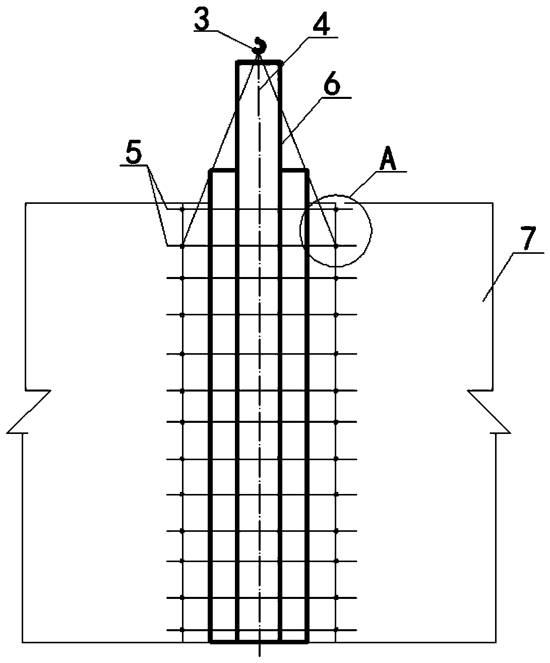
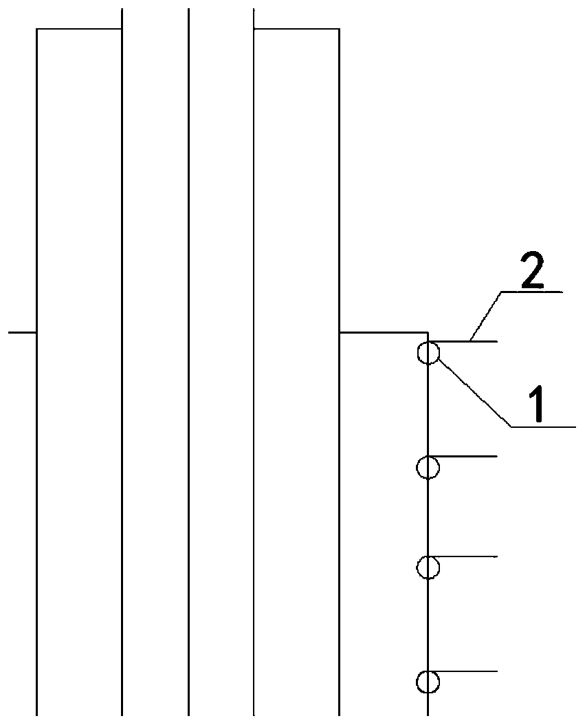
[0022] see Figure 1-2 , an embodiment provided by the present invention: a method for installing a large-area lightweight aggregate buttress column, which is used in the buttress column technology of industrial and civil buildings, and makes shaped steel formwork according to the design shape and size requirements, and the longitudinal 1. Set steel wires at equal intervals in the horizontal direction, and set steel wires bent at 90° at equal interv


PUM

PropertyMeasurementUnit
Thicknessaaaaaaaaaa
Diameteraaaaaaaaaa
Thicknessaaaaaaaaaa

Abstract

The invention discloses a method for installing a large-area lightweight aggregate wall-supporting column, relating to the technical field of building construction. The method for installing a large-area lightweight aggregate wall-supporting column is used for an industrial and civil building wall-supporting column process. The method is used for manufacturing a shaping steel template according todesign shape and size requirements, and steel wires are arranged at equal intervals in the longitudinal direction and the transverse direction of the shaping steel template, and the steel wires whichare bent by 90 degrees are arranged at equal intervals in the longitudinal direction of the shaping steel template, and the shaping steel template is paved on the outdoor ground, and a protective layer mortar cushion block is arranged on the shaping steel template, and light aggregate concrete is poured, and the template is disassembled after natural curing for 7 days. According to the invention,by adopting a section-by-section fixed installation method, the construction time of the wall -supporting column can be greatly shortened, further, the possibility that the wall thickness of the wall-supporting column is too thin to control the concrete pouring molding quality easily and quality hidden dangers such as honeycomb, cavities, exposed ribs and the like are easy to appear is reduced, thereby achieving the purpose of fast construction of the wall supporting column.

Description


Claims


Application Information

Patent Timeline
Owner CHINA MCC17 GRP
Why Eureka
Try Eureka