Built-in vibrating device based on sleeve post-grouting construction

A technology of a vibrating device and a vibration exciting device, which is applied in the processing of building materials, structural elements, building components, etc., can solve the problem that the compactness of the grouting layer and the grouting sleeve cannot be guaranteed, and the risk of lower steel bars being pulled out increases. , Affect the connection quality at the nodes and other problems, to achieve the effect of improving the overall compactness, easy installation, and improving the compressive strength

Active Publication Date: 2019-05-10
SOUTHEAST UNIV
View PDF7 Cites 2 Cited by
  • Summary
  • Abstract
  • Description
  • Claims
  • Application Information

AI Technical Summary

Problems solved by technology

However, due to the characteristics of large amount of grouting and long time, the compactness of the sitting grout layer and the grouting slee

Method used


Image

  • Built-in vibrating device based on sleeve post-grouting construction
  • Built-in vibrating device based on sleeve post-grouting construction
  • Built-in vibrating device based on sleeve post-grouting construction

Examples


Embodiment

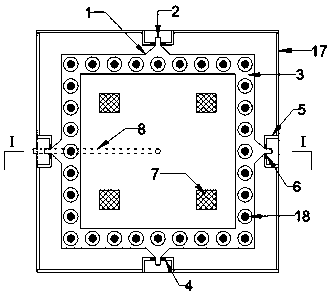
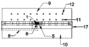
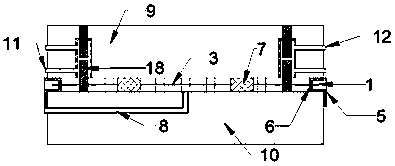
[0028] As shown in the figure, a built-in vibrating device based on post-sleeve grouting construction according to the present invention includes a vibrating ring 1, a plurality of limit supports 4 and a vibrating device 15, and the vibrating ring 1 has a rough surface , can drive more grouting material when vibrating; the vibrating ring 1 includes four convex mouths 2 and a vibrating main ring 3, and the convex mouths 2 are evenly distributed in the center of the four directions of the vibrating main ring 3, and are used to communicate with the exciting device 15 Connection; steel bar holes are reserved on the vibrating main ring 3 for the lower steel bars 18 to pass through. The limit support 4 is used to fix the vibrating ring 1, and it includes a rectangular groove 5 and a rubber limit plug 6. The front of the rectangular groove 5 is provided with a lower stopper, and the stopper is provided with a bolt hole, and the rectangular groove can be connected by a bolt. 5 is fixed o


PUM


Abstract

The invention discloses a built-in vibrating device based on sleeve post-grouting construction. The device comprises a vibrating ring, a plurality of limiting supports and a vibration excitation device, wherein the vibration ring comprises a convex nozzle and a vibration main ring, the vibration excitation device comprises a clamping nozzle and an internal vibration excitation system, and the clamping nozzle is meshed with the convex nozzle to enable the vibration main ring to vibrate under the action of the internal vibration excitation system. The limiting support comprises a rectangular groove and a rubber limiting plug and is used for fixing the vibration ring. The device has the advantages of being convenient to install and easy to operate, the compactness of the grouting material forsleeve post-grouting construction can be effectively improved, and the connecting quality of components is guaranteed.

Description


Claims


Application Information

Patent Timeline
Owner SOUTHEAST UNIV
Why Eureka
Try Eureka