Assessment method for electric generator inertia control ability of multiloop VSC-HVDC direct current system

A VSC-HVDC, DC system technology, applied in the field of multi-circuit VSC-HVDC DC system evaluation of generator inertial control capability, can solve the problems of dependent system model, complex dynamic characteristics, poor robustness, etc., to achieve strong robustness sexual effect

Inactive Publication Date: 2019-05-10
SOUTH CHINA UNIV OF TECH
View PDF0 Cites 2 Cited by
  • Summary
  • Abstract
  • Description
  • Claims
  • Application Information

AI Technical Summary

Problems solved by technology

However, the detailed dynamic characteristics of VSC-HVDC are relatively complex, and the topology of large-scale power grids is also relatively cha

Method used


Image

  • Assessment method for electric generator inertia control ability of multiloop VSC-HVDC direct current system
  • Assessment method for electric generator inertia control ability of multiloop VSC-HVDC direct current system
  • Assessment method for electric generator inertia control ability of multiloop VSC-HVDC direct current system

Examples


Example Embodiment

[0015] Examples:

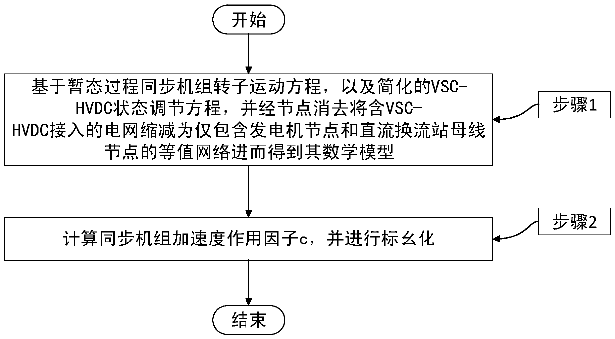
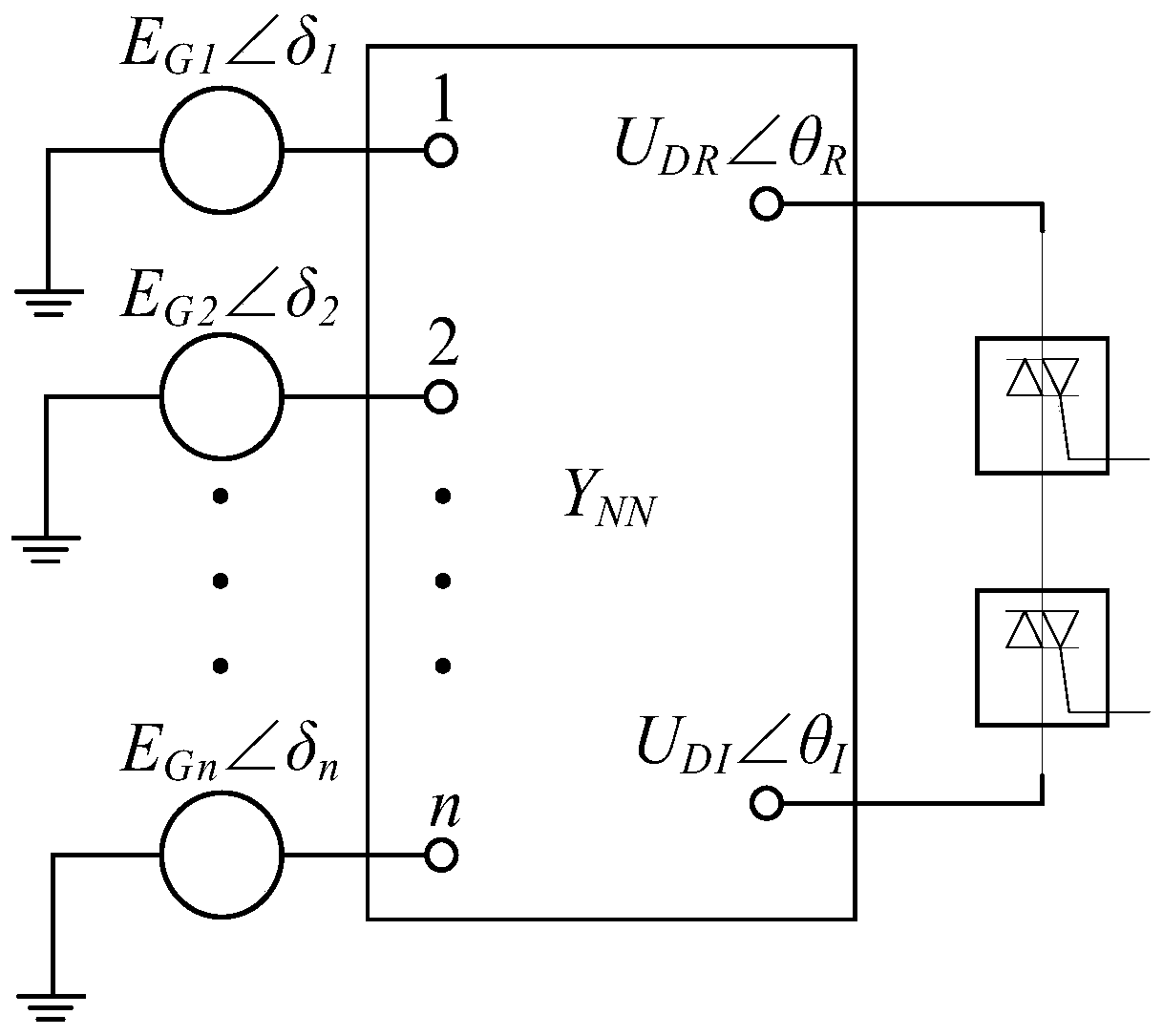
[0016] In this embodiment, based on the simplified VSC-HVDC model and the rotor equation of the synchronous unit, a multi-circuit VSC-HVDC DC system is designed to evaluate the inertial control capability of the generator to evaluate the VSC-HVDC DC system in different operating modes. The inertia control capability of the system to the generator. The implementation flow diagram of the method is as follows figure 1 As shown, the equivalent model of the power system with VSC-HVDC access is as figure 2 As shown, it specifically includes the following steps:

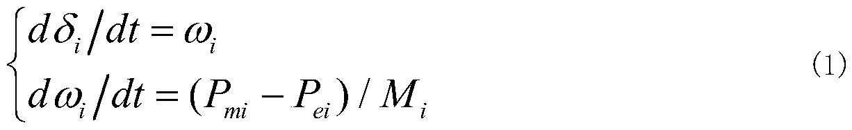
[0017] Step 1. Synchronize the rotor motion equation of the generator set based on the transient process and the simplified VSC-HVDC state adjustment equation, and reduce the power grid with VSC-HVDC access to only the generator node and the DC converter station bus node through node elimination The equivalent network of then obtains its mathematical model;

[0018] Step 2. In the steady state of the system, cal


PUM


Abstract

The invention discloses an assessment method for electric generator inertia control ability of a multiloop VSC-HVDC direct current system. The method comprises the following steps: step 1, based on atransient process synchronous generator rotor motion equation and a simplified VSC-HVDC state regulation equation, and by node removal, a power network containing VSC-HVDC access is reduced to be an equivalent network only containing an electric generator node and a direct current converter station bus node, and consequently, a mathematic model thereof is obtained; step 2, under a system steady state condition, a synchronous generator acceleration action factor c is calculated and subjected to per unit treatment, and the c is used for reflecting controllability of the VSC-HVDC to different synchronous generators and transient information of each synchronous generator. The assessment method has no need of a detailed model of the system, and has very high robustness to different operating modes of the system.

Description


Claims


Application Information

Patent Timeline
Owner SOUTH CHINA UNIV OF TECH
Why Eureka
Try Eureka