Cantilever type polar coordinate feeding 3D printer

A 3D printer and polar coordinate technology, applied in the field of 3D printing, can solve problems such as inability to achieve energy saving effects, multiple power sources, and heavy weight, and achieve high engineering practical value, simple structure, and convenient maintenance

Pending Publication Date: 2019-05-17
SHAANXI SCI TECH UNIV
View PDF4 Cites 1 Cited by
  • Summary
  • Abstract
  • Description
  • Claims
  • Application Information

AI Technical Summary

Problems solved by technology

Common desktop-level 3D printers are gantry-type three-coordinate 3D printers, which have been widely used for their structural stability and long-term performance. The space

Method used


Image

  • Cantilever type polar coordinate feeding 3D printer
  • Cantilever type polar coordinate feeding 3D printer
  • Cantilever type polar coordinate feeding 3D printer

Examples


Embodiment Construction

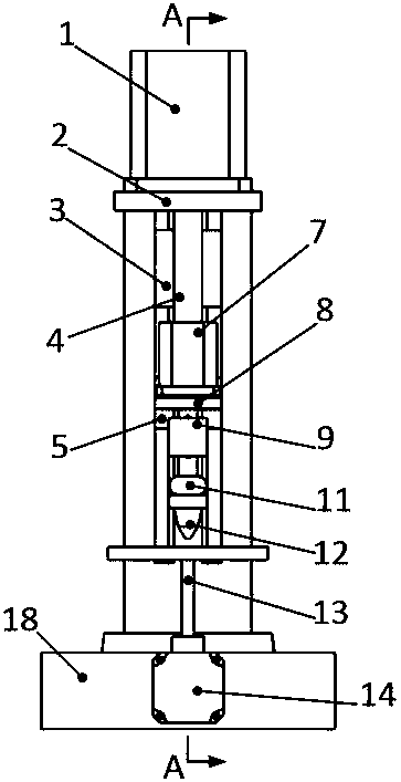
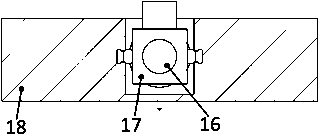
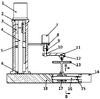
[0013] The implementation process of the present invention will be described below in conjunction with the accompanying drawings.

[0014] Such as figure 1 , figure 2 and image 3 As shown, a cantilever type polar coordinate feeding 3D printer includes a base motor 1, a base shell 2, a base coupling 3, a lead screw 4, a nut 5, a bearing 6, a cantilever motor 7, a bracket 8, a cantilever coupling Shaft device 9, connecting rod 10, cantilever 11, printing nozzle 12, printing platform 13, motor 14, coupling 15, screw rod 16, sliding nut 17, base 18; The base motor 1 is installed on the upper side of the base housing 2 through bolts, the motor shaft of the base motor 1 and the side with the keyway of the lead screw 4 are connected by a key through the base coupling 3, and the other side of the lead screw 4 is installed on the Supported in the bearing 6 at the bottom of the machine base shell 2, the screw 4 is fitted with a nut 5, and the bracket 8 protruding from the nut 5 protru


PUM


Abstract

The invention discloses a cantilever type polar coordinate feeding 3D printer. The cantilever type polar coordinate feeding 3D printer is composed of three parts including a 3D printer seat, a rotating arm mechanism and an electric push cylinder; the 3D printer seat is installed on the upper part of a base, the rotating arm mechanism is installed on a cantilever stretching out from the 3D printerseat, the electric push cylinder is installed on the other side of the base, and the cantilever type polar coordinate feeding 3D printer is formed. According to the cantilever type polar coordinate feeding 3D printer, polar coordinate movement of the cantilever type 3D printer is controlled through motors to realize the optimization of the volume structure of a desktop 3D printer, the weight of aprinting head is reduced, the printing precision is improved, and the printing efficiency is improved by direct driving by the motors; and the cantilever type polar coordinate feeding 3D printer has the advantages that the stability and the reliability are achieved, the space occupancy rate is low, and the printing is continuous and accurate, and later maintenance is convenient.

Description


Claims


Application Information

Patent Timeline
Owner SHAANXI SCI TECH UNIV
Why Eureka
Try Eureka