Connecting device for electrical parameter measurement of low-voltage switch cabinet drawer

A low-voltage switchgear and electrical parameter technology, applied to the direction of the measuring device shell, etc., can solve the problems affecting the quality and efficiency of maintenance, the difficulty of measurement operation, and inaccurate measurement, so as to save measurement working time, reduce error identification, and improve work efficiency. Effect

Pending Publication Date: 2019-05-28
JIANGSU NUCLEAR POWER CORP
View PDF0 Cites 0 Cited by
  • Summary
  • Abstract
  • Description
  • Claims
  • Application Information

AI Technical Summary

Benefits of technology

This patented technology helps measure electricity quality more efficiently with less effort compared to traditional methods like manual measurements or laborious procedures that require multiple tools at different locations. It also includes improvements such as extending the terminal ends easily enough without sacrificing their functionality, increasing stability while being able to accurately determine voltage levels, reducing confusion during testing, enabling ease of use when carrying it out indoors, smaller size, portable design, and easier transportation than previous solutions.

Problems solved by technology

This patented technical solution described in this patents relates to improving the accuracy and performance of testing low voltage switchgears (LSS) without having extra equipment or slow down their measurements processes due to limited accessibility inside the unit's cabinet.

Method used


Image

  • Connecting device for electrical parameter measurement of low-voltage switch cabinet drawer
  • Connecting device for electrical parameter measurement of low-voltage switch cabinet drawer

Examples


Embodiment 1

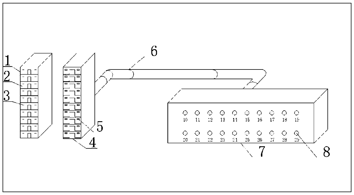
[0029] Such as figure 1 As shown, a connection device for measuring electrical parameters of a low-voltage switchgear drawer provided by the present invention includes a full-size low-voltage switchgear drawer terminal row 1, terminal intervals 2, flat sheet-shaped terminals 3, connecting plug 4, flat sheet-shaped hollow Terminal 5, connecting cable 6, terminal box 7, measuring hole 8; connecting plug one 4 is connected to terminal box 7 through connecting cable 6, connecting plug one 4 is provided with several flat sheet-shaped hollow terminals 5, full-sized low-voltage The terminal block 1 of the switch cabinet drawer is provided with a terminal interval 2, and the terminal interval 2 is provided with a flat sheet-shaped terminal 3 matched with a flat sheet-shaped hollow terminal 5. Several measuring holes 8 are provided on the terminal box 7 .

[0030] Connect the terminals used in the control circuit of the drawer and the interface circuit of the instrument and electricity t

Embodiment 2

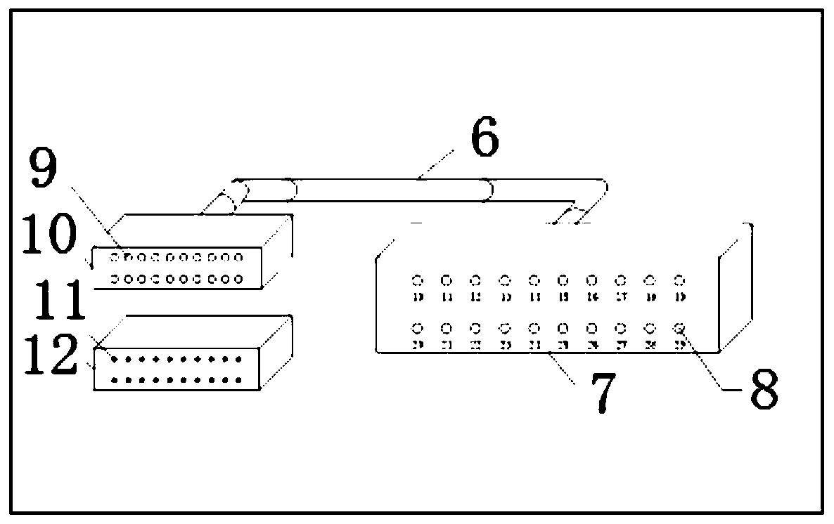
[0032] Such as figure 2 As shown, a connection device for measuring electrical parameters of a low-voltage switch cabinet drawer provided by the present invention includes a connection cable 6, a terminal box 7, a measurement hole 8, a tubular hollow terminal 9, a connecting plug 10, a needle terminal 11, a The drawer terminal row 12 of the full-size low-voltage switch cabinet; the connecting plug 2 10 is connected to the terminal box 7 through the connecting cable 6, the connecting plug 2 10 is provided with a tubular hollow terminal 9, and the drawer terminal row 12 of the non-full-size low-voltage switch cabinet is provided with The needle-shaped terminal 11 , the needle-shaped terminal 11 can match with the tubular hollow terminal 9 . Several measuring holes 8 are provided on the terminal box 7 .

[0033] Connect the terminals used in the control circuit of the drawer and the interface circuit of the instrument and electricity through the matching connecting plug and cable


PUM


Abstract

The invention belongs to the technical field of nuclear power plant electrical maintenance, and particularly relates to a connecting device for electrical parameter measurement of a low-voltage switchcabinet drawer. The connecting device comprises a full-size low-voltage switch cabinet drawer terminal strip, terminal intervals, flat-sheet-shaped terminals, a first connecting plug, flat-sheet-shaped hollow terminals, a connecting cable, a terminal connection box and measuring holes. The first connecting plug is connected with the terminal connection box through the connecting cable. The multiple flat-sheet-shaped hollow terminals are arranged on the first connecting plug. The terminal intervals are arranged on the full-size low-voltage switch cabinet drawer terminal strip and provided withthe flat-sheet-shaped terminals matched with the flat-sheet-shaped hollow terminals. The multiple measuring holes are formed in the terminal connection box. Through the connecting device, working efficiency can be improved, working time can be shortened, and the reliability of measurement is improved greatly.

Description


Claims


Application Information

Patent Timeline
Owner JIANGSU NUCLEAR POWER CORP
Why Eureka
Try Eureka