Intelligent ash conveying method and device for power plant

An ash conveying and power plant technology, applied in conveyor control devices, transportation and packaging, conveyors, etc., can solve the problems of low ash conveying efficiency and easy occurrence of accidents, and achieve the effect of reducing resource waste and reducing system ash blocking.

Active Publication Date: 2019-06-07
NORTH CHINA ELECTRICAL POWER RES INST +1
View PDF10 Cites 5 Cited by
  • Summary
  • Abstract
  • Description
  • Claims
  • Application Information

AI Technical Summary

Problems solved by technology

[0005] In order to solve the problems of prone to accidents and low efficiency of ash transportation in the existing ash transportation te

Method used


Image

  • Intelligent ash conveying method and device for power plant
  • Intelligent ash conveying method and device for power plant

Examples


Embodiment Construction

[0027] The embodiment of the present invention provides a method and device for intelligent ash transportation in a power plant.

[0028] The following will clearly and completely describe the technical solutions in the embodiments of the present invention with reference to the accompanying drawings in the embodiments of the present invention. Obviously, the described embodiments are only some, not all, embodiments of the present invention. Based on the embodiments of the present invention, all other embodiments obtained by persons of ordinary skill in the art without creative efforts fall within the protection scope of the present invention.

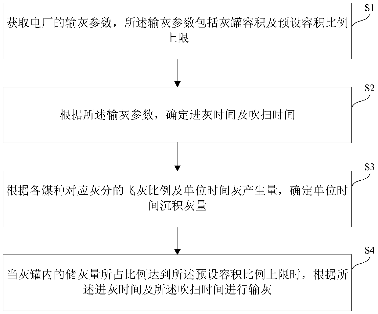
[0029] Such as figure 1 Shown is a flow chart of an intelligent ash delivery method for a power plant according to an embodiment of the present invention. The method shown in the figure includes: step S1, obtaining the ash delivery parameters of the power plant, and the ash delivery parameters include the volume of the ash tank and the pre


PUM


Abstract

The invention provides an intelligent ash conveying method and device for a power plant. The method comprises the steps of acquiring the ash conveying parameters of the power plant, wherein the ash conveying parameters comprise the volume of an ash tank and a preset volume ratio upper limit; determining the ash inlet time and purging time according to the ash conveying parameters; determining theash deposition amount per unit time according to the flying ash proportion of ash contents corresponding to different coal types and the quantity of generated ash per unit time; and conveying ash according to the ash inlet time and the purging time when the proportion of the ash storage amount in the ash tank reaches the preset volume ratio upper limit. According to the intelligent ash conveying method, by considering the actual conditions of ash falling in an ash bucket, intelligent ash conveying is achieved, and the occurrence probability of ash clogging of a system is reduced; and meanwhilethe situation of resource waste is reduced greatly.

Description


Claims


Application Information

Patent Timeline
Owner NORTH CHINA ELECTRICAL POWER RES INST
Why Eureka
Try Eureka