Phase change material filling equipment with replaceable screen plate
A technology of phase change materials and filling equipment, which is applied in the direction of liquid materials, packaging, transportation and packaging, etc., can solve the problems of cumbersome process, long filling cycle, and low production efficiency, and achieve simple filling process and short filling cycle Short, easy-to-use effects
- Summary
- Abstract
- Description
- Claims
- Application Information
AI Technical Summary
Problems solved by technology
Method used
Image

Examples
Example Embodiment
[0049] Example 1
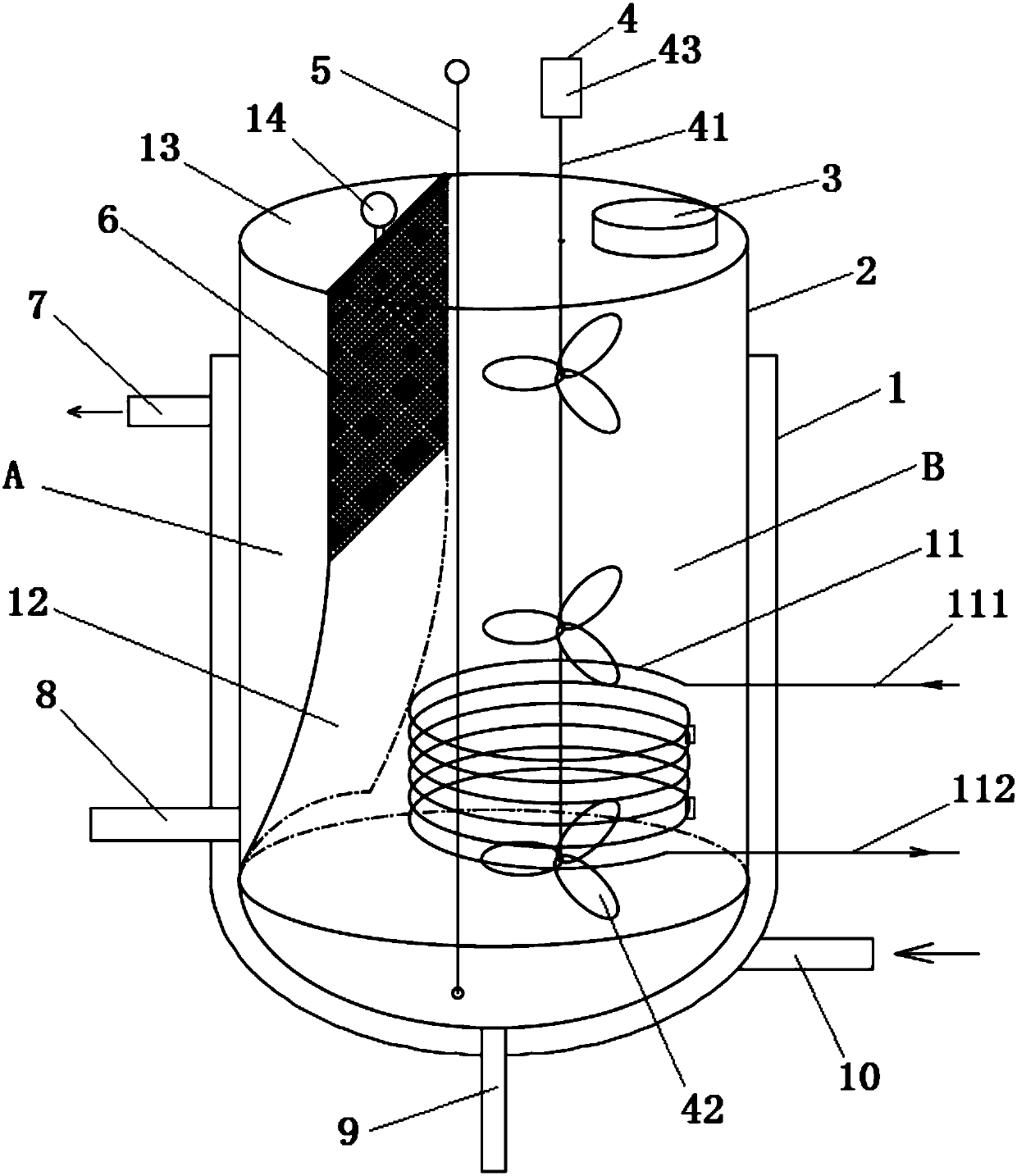
[0050]A phase-change material filling equipment with a replaceable sieve plate 6, comprising a vertically arranged jacket 1 with an open top, inside the jacket 1 is vertically arranged a storage tank 2 with a closed top, the The side wall of the storage tank 2 is 1 / 4 away from the top surface and is tightly connected with the top of the jacket 1 so that a closed cavity is formed between the storage tank 2 and the jacket 1, and a top plate 13 is arranged on the top of the top plate 13. Strip-shaped hollow groove, the two ends of the hollow groove extend to the edge of the top plate 13 respectively, and the left side of the storage tank 2 is located directly below the above-mentioned strip-shaped hollow groove. The fixed plate 12 in the area, the left and right sides are respectively the discharge area A and the heating area B, the bottom of the fixed plate 12 is bent to the left, so that the heating space at the bottom of the heating area B is more sufficient,
Example Embodiment
[0059] Example 2
[0060] A phase-change material filling equipment with a replaceable sieve plate 6, comprising a vertically arranged jacket 1 with an open top, inside the jacket 1 is vertically arranged a storage tank 2 with a closed top, the The side wall of the storage tank 2 is 1 / 6 away from the top surface and is sealed and connected with the top of the jacket 1 so that a closed cavity is formed between the storage tank 2 and the jacket 1, and a top plate 13 is arranged on the top of the top plate 13. Strip-shaped hollow groove, the two ends of the hollow groove extend to the edge of the top plate 13 respectively, and the left side of the storage tank 2 is located directly below the above-mentioned strip-shaped hollow groove. The fixed plate 12 in the area, the left and right sides are respectively the discharge area A and the heating area B, the bottom of the fixed plate 12 is bent to the left, so that the heating space at the bottom of the heating area B is more suffici
PUM
| Property | Measurement | Unit |
|---|---|---|
| Diameter | aaaaa | aaaaa |
Abstract
Description
Claims
Application Information
 - R&D Engineer
- R&D Manager
- IP Professional
- Industry Leading Data Capabilities
- Powerful AI technology
- Patent DNA Extraction
Browse by: Latest US Patents, China's latest patents, Technical Efficacy Thesaurus, Application Domain, Technology Topic.
© 2024 PatSnap. All rights reserved.Legal|Privacy policy|Modern Slavery Act Transparency Statement|Sitemap