Test device and test method for simulating soil mass column hole expansion

A test device and soil simulation technology, applied in the field of geotechnical engineering, can solve problems such as remodeling, difficult to solve complex strata, disturbance, etc., and achieve the effects of strong operability, ingenious test methods, and improved test accuracy

Active Publication Date: 2019-07-05
TAIYUAN UNIV OF TECH
View PDF10 Cites 2 Cited by
  • Summary
  • Abstract
  • Description
  • Claims
  • Application Information

AI Technical Summary

Problems solved by technology

However, during the process of expansion and extrusion, the soil often undergoes disturbance, remodeling, structural damage or excess pore wate

Method used


Image

  • Test device and test method for simulating soil mass column hole expansion
  • Test device and test method for simulating soil mass column hole expansion
  • Test device and test method for simulating soil mass column hole expansion

Examples


Embodiment 1

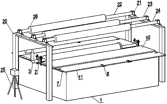
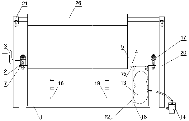
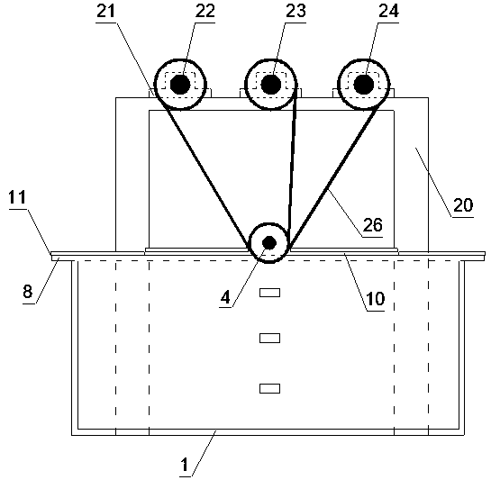
[0040] Such as Figure 1~7As shown, the present invention provides a kind of test device for simulating the expansion of column holes in soil, including model box 1, portal frame 20, soil squeezing device, high-speed camera 25, confining pressure device and data acquisition device;

[0041] Described model box 1 is cuboid structure, and one short side of it adopts toughened glass plate to make, and high-speed camera 25 faces this transparent glass surface, and the short side length of model box 1 must satisfy the need to eliminate box wall to soil column hole expansion. Influence: the short side direction of the box top of the model box 1 is provided with a first outrigger plate 7, and two second outrigger plates 8 are arranged at equal intervals in the long side direction;

[0042] The door-shaped support 20 stands on both sides of the short side direction of the model box 1, and the door-shaped support 20 is composed of a crossbeam and two columns, and the bottom of the column


PUM


Abstract

The invention discloses a test device and a test method for simulating soil mass column hole expansion. The test device comprises a model box, a door type bracket, a soil compacting device, a high-speed video camera, a confining pressure device and a data acquisition device, wherein the model box is of a rectangular parallelepiped structure, one short edge side surface thereof is made of a tempered glass plate, the high-speed video camera directly faces the transparent glass surface, the door type bracket is erected on two sides of the model box in the short edge direction, and the soil compacting device comprises a roller shaft assembly, a hanging cloth, a crank handle and a cover plate; and the confining pressure device is arranged on the other side corresponding to the transparent glassof the model box, and comprises an air bag, a loading plate, a partition plate and a vacuum pump; and the data acquisition device comprises a load cell, a pore water pressure gauge and an earth pressure box. The test device and the test method realize the synchronous dynamic test of the soil compacting effect, and overcome the deficiency that the prior art can only study the soil mass column holeexpansion through theoretical analysis.

Description


Claims


Application Information

Patent Timeline
Owner TAIYUAN UNIV OF TECH
Why Eureka
Try Eureka