Terminal equipment

A technology of terminal equipment and telescopic brackets, which is applied in the field of communication, can solve the problems of difficult structural design of terminal equipment and space occupation of terminal equipment, and achieve the effects of improved resource occupation, reduced space, and simple structural design

Active Publication Date: 2019-07-23
VIVO MOBILE COMM HANGZHOU CO LTD
View PDF6 Cites 10 Cited by
  • Summary
  • Abstract
  • Description
  • Claims
  • Application Information

AI Technical Summary

Problems solved by technology

[0005] The invention discloses a terminal device to solve the problem that a plurality of optical devices will occupy the space of the terminal device, which makes the structural design of the terminal device more difficult

Method used


Image

  • Terminal equipment
  • Terminal equipment
  • Terminal equipment

Examples


Example Embodiment

[0028] In order to make the objectives, technical solutions and advantages of the present invention clearer, the technical solutions of the present invention will be described clearly and completely in conjunction with specific embodiments of the present invention and the corresponding drawings. Obviously, the described embodiments are only a part of the embodiments of the present invention, rather than all the embodiments. Based on the embodiments of the present invention, all other embodiments obtained by those of ordinary skill in the art without creative work shall fall within the protection scope of the present invention.

[0029] The technical solutions disclosed in the various embodiments of the present invention will be described in detail below with reference to the accompanying drawings.

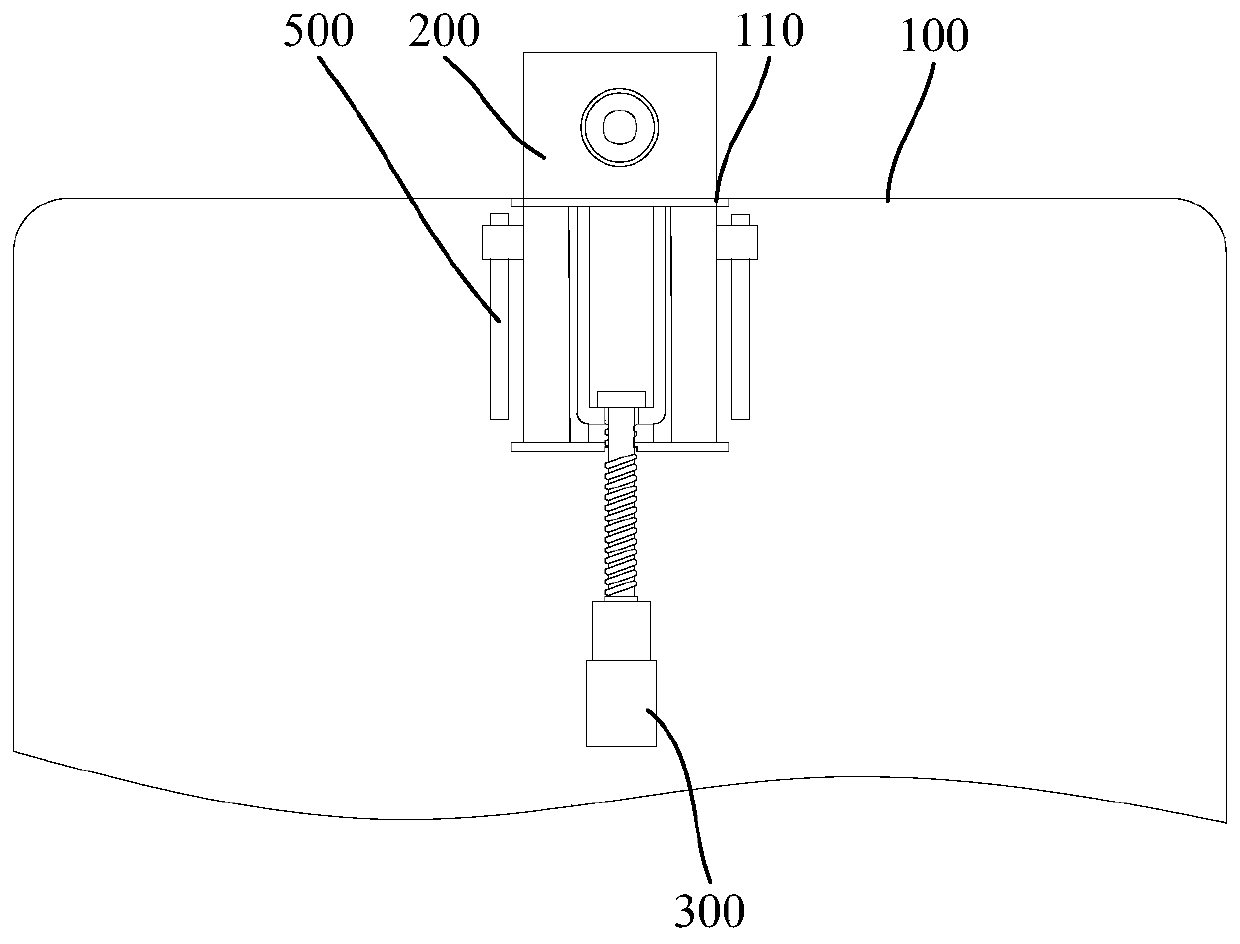
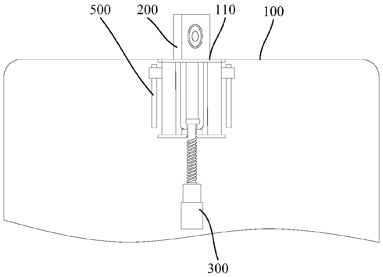
[0030] Such as Figure 1-Figure 8 As shown, the embodiment of the present invention discloses a terminal device, which includes a housing 100, a driven device 200, and a driving mechanism


PUM


Abstract

The invention discloses terminal equipment. The terminal equipment comprises a shell, a driven device and a drive mechanism. The shell is provided with a penetration hole. The driven device comprisesan optical device, a telescopic support and a rotary support. One end of the rotary support is fixedly connected with the optical device, a first opening is formed in the other end of the rotary support, a first connecting part is arranged on the rotary support, and at least part of the rotary support is arranged in the telescopic support. The telescopic support abuts against the rotary support orthe optical device, a second opening is formed in the portion, corresponding to the first opening, of the telescopic support, and a first thread section is arranged in the second opening. The drive mechanism is arranged in the shell, and comprises a drive source and a lead screw. One end of the lead screw is connected with the drive source, and the other end of the drive mechanism is connected with a second connecting part. The lead screw comprises a second thread section and a polished rod section, the polished rod section stretches into the rotary support to be connected with the second connecting part, and when the second thread section and the first thread section are in threaded connection, the lead screw drives the telescopic support to move close to or away from the penetration hole. The terminal equipment is simpler in structural design.

Description


Claims


Application Information

Patent Timeline
Owner VIVO MOBILE COMM HANGZHOU CO LTD
Why Eureka
Try Eureka