Resistive high-sensitivity flexible pressure sensor device

A pressure sensor, resistive technology, applied in the field of sensing devices, can solve the problems of limit output resistance reduction, sacrifice of measurement sensitivity, output mutation, etc.

Active Publication Date: 2019-07-26
深圳市航天新材科技有限公司 +1
View PDF17 Cites 3 Cited by
  • Summary
  • Abstract
  • Description
  • Claims
  • Application Information

AI Technical Summary

Benefits of technology

This technology allows for creation of an electronic device called a flexure sensor by combining two layers: one made from conductive materials like metal or plastic; another material used instead of metallic ones (pressures). When pressed together they work differently due to their differences in electrical properties such as capacitance between them. These devices are highly sensitive but have very little variation over time even when placed under constant stress conditions. They also produce small changes in voltage levels without changing anything outside this measurement range.

Problems solved by technology

The present technology relating to making flexible electronic devices involves creation of highly sensitive pressure sensers for use in applications where there may exist strong forces such as when they come close together during flight operations. Current methods involve adding layers onto these types of sensors without changing their properties due to changes caused by environmental factors like temperature. This results in decreased accuracy over longer periods of operation compared to previous designs.

Method used


Image

  • Resistive high-sensitivity flexible pressure sensor device
  • Resistive high-sensitivity flexible pressure sensor device
  • Resistive high-sensitivity flexible pressure sensor device

Examples


example 1

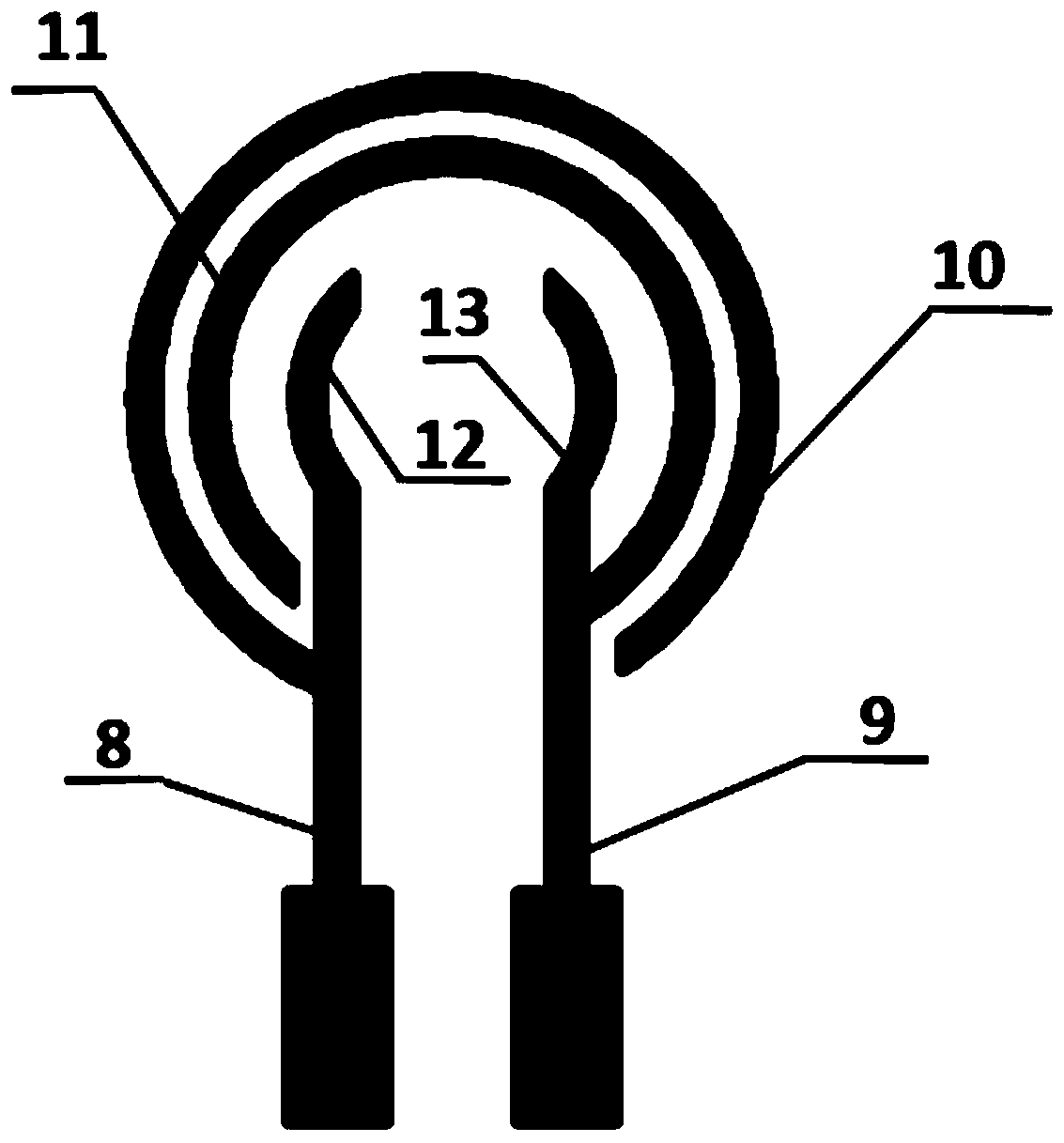
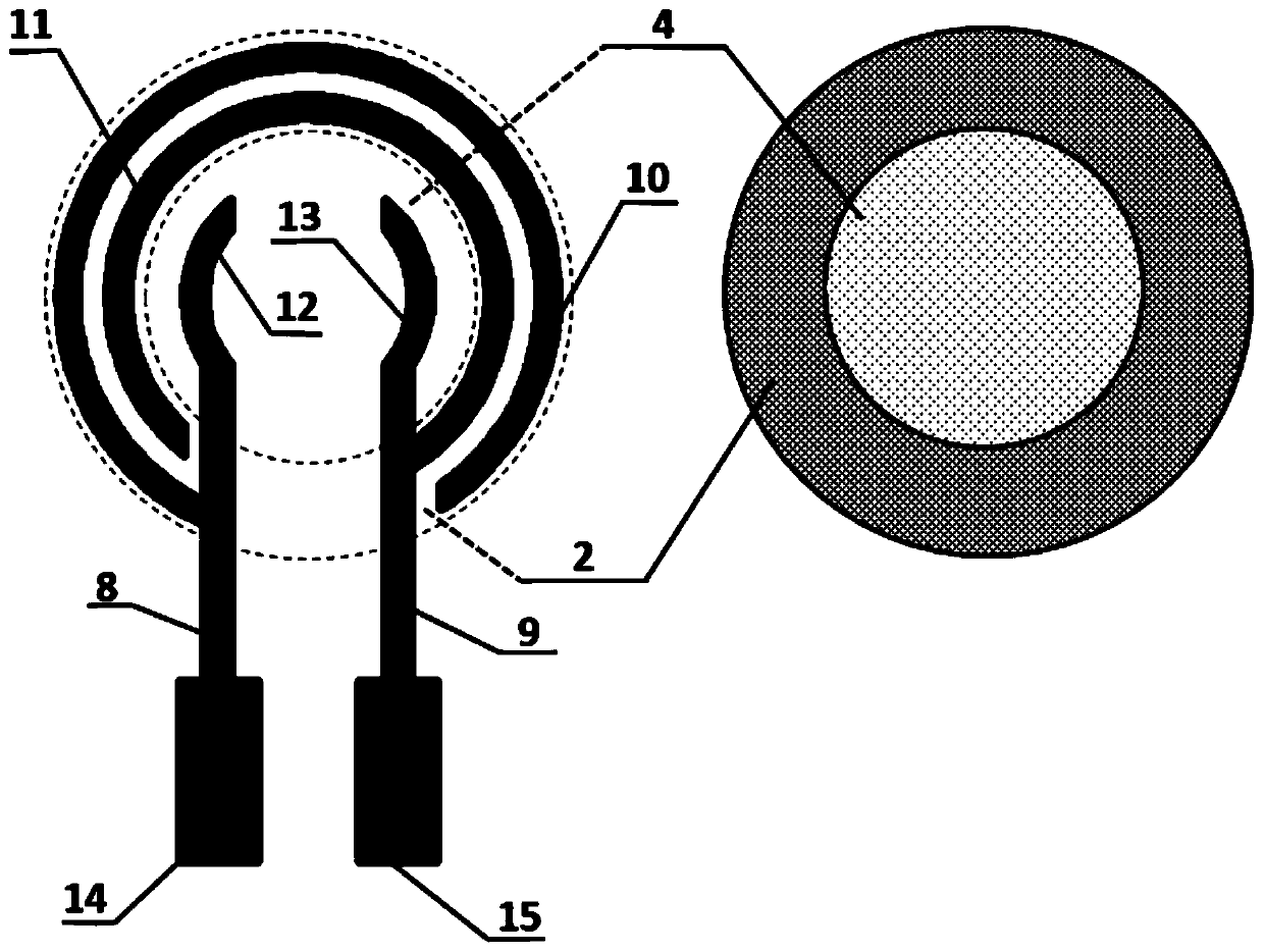
[0052] Such as Figure 1 to Figure 5 As shown, the circuit width in the ring electrode 5 is 0.5mm, the first central electrode circuit 12 and the second central electrode circuit 13 are concentric circular arcs with a radius of R1=2mm, the first central electrode circuit 12 and the second central electrode circuit 13 spacing D1=3mm, first outer ring electrode circuit 10 arc radius R2=3.5mm, second outer ring electrode circuit 11 arc radius R3=4.5mm, first center electrode circuit 12 and first outer ring electrode circuit The spacing D2 of 10 = 1 mm, and the spacing D3 = 0.5 mm between the first outer ring electrode circuit 10 and the second outer ring electrode circuit 11 . The length D4 of the first electrode lead-out end 8 and the second electrode lead-out end 9 is 3 mm, and the dimensions of the first test port 14 and the second test port 15 are D5 = 3.5 mm and D6 = 1.5 mm.

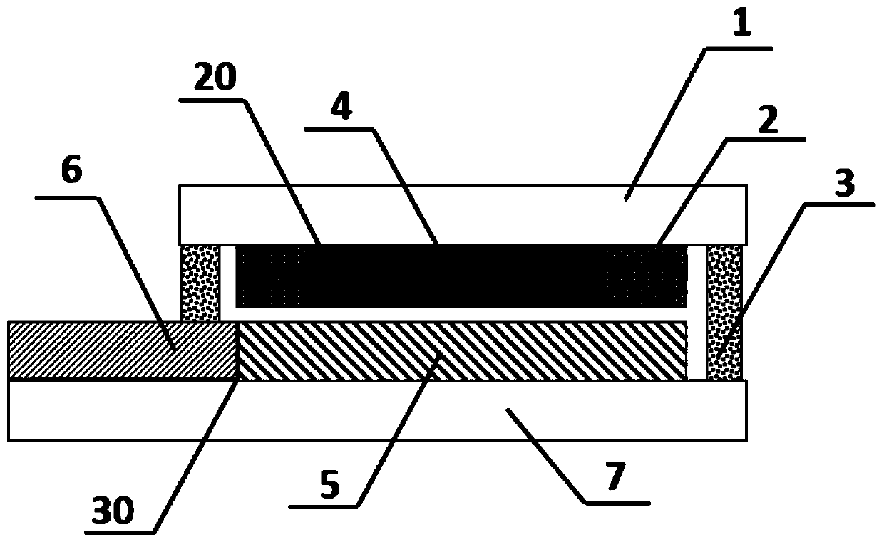
[0053] The inner ring pressure-sensitive layer 4 is a circular structure with a radius of R5=3.3mm, t

Embodiment 1

[0062] Implement the sensor performance test described in example 1:

[0063] Connect the first test port 14 and the second test port 15 in the prepared pressure sensor electrode to the processor module and the power supply module, and use the Japanese graphic high-speed recorder (GL900APS) to test its output under different pressure states voltage changes.

[0064] In this implementation example, the voltage provided to the sensor is 2.7V. When no external force acts on the surface of the sensor, the output voltage of the pressure sensor is 2.7V; when the applied external force is less than 20N, the output voltage of the pressure sensor is still about 2.7V without significant change. It is because the adhesive material used in packaging has a certain thickness, so that the pressure-sensitive layer and the electrode are separated by a certain distance in the initial state, so under a small external force, the pressure-sensitive layer and the electrode do not come into contact, an


PUM


Abstract

The invention provides a resistive high-sensitivity flexible pressure sensor device comprising a first flexible film substrate, a pressure sensitive layer, a ring electrode layer and a second flexiblefilm substrate which are laminated, wherein the pressure sensitive layer is located between the first flexible film substrate and the ring electrode layer, the ring electrode layer is located betweenthe pressure sensitive layer and the second flexible film substrate, the ring electrode layer comprises a ring electrode and an electrode lead end, the ring electrode is connected to the electrode lead end, the first flexible film substrate and the second flexible film substrate are encapsulated by an adhesive material, the pressure sensitive layer comprises an outer ring pressure sensitive layerand an inner ring pressure sensitive layer on the same plane, the diameter of the outer ring pressure sensitive layer is greater than that of the inner ring pressure sensitive layer, and the surfaceresistance of the inner ring pressure sensitive layer is greater than that of the outer ring pressure sensitive layer. The resistive high-sensitivity flexible pressure sensor device has the beneficialeffects of having both high sensitivity and no mutation in the range output curve.

Description


Claims


Application Information

Patent Timeline
Owner 深圳市航天新材科技有限公司
Why Eureka
Try Eureka