Pressure relief structure for pressure cooker, pressure cooker cover and pressure cooker

A pressure relief structure, pressure cooker technology, applied in pressure cooker, application, household utensils, etc., can solve problems such as poor cooking effect, explosion, incorrect operation, etc., and achieve the effect of novel design, convenient use and wide application range

Active Publication Date: 2019-08-16
武义伟诺工贸有限公司
View PDF5 Cites 0 Cited by
  • Summary
  • Abstract
  • Description
  • Claims
  • Application Information

AI Technical Summary

Benefits of technology

This new feature allows for easy control over how hot foods are served by an electric rice heat press or other type of device. By controlling the movement of the screw mechanism inside it, users have more flexibility than previous designs because they only had one setting on their machine's settings. They could also custom-tailor this function based upon user preferences without having to manually reprogram them every time.

Problems solved by technology

Technological Problem: Existing pressure cookors have limitations in achieving efficient steam sterilization due to their lack of adjustable pressure release mechanisms for different types of liquids such as hot potatoes and fried rice. This results in unsafe conditions during use which could result from overpressurizing certain parts inside these systems causing damage.

Method used


Image

  • Pressure relief structure for pressure cooker, pressure cooker cover and pressure cooker
  • Pressure relief structure for pressure cooker, pressure cooker cover and pressure cooker
  • Pressure relief structure for pressure cooker, pressure cooker cover and pressure cooker

Examples


Embodiment 1

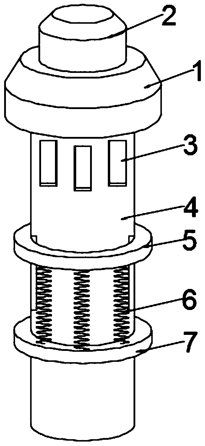
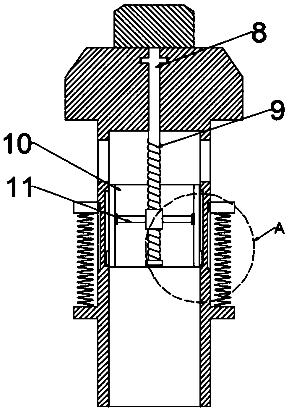
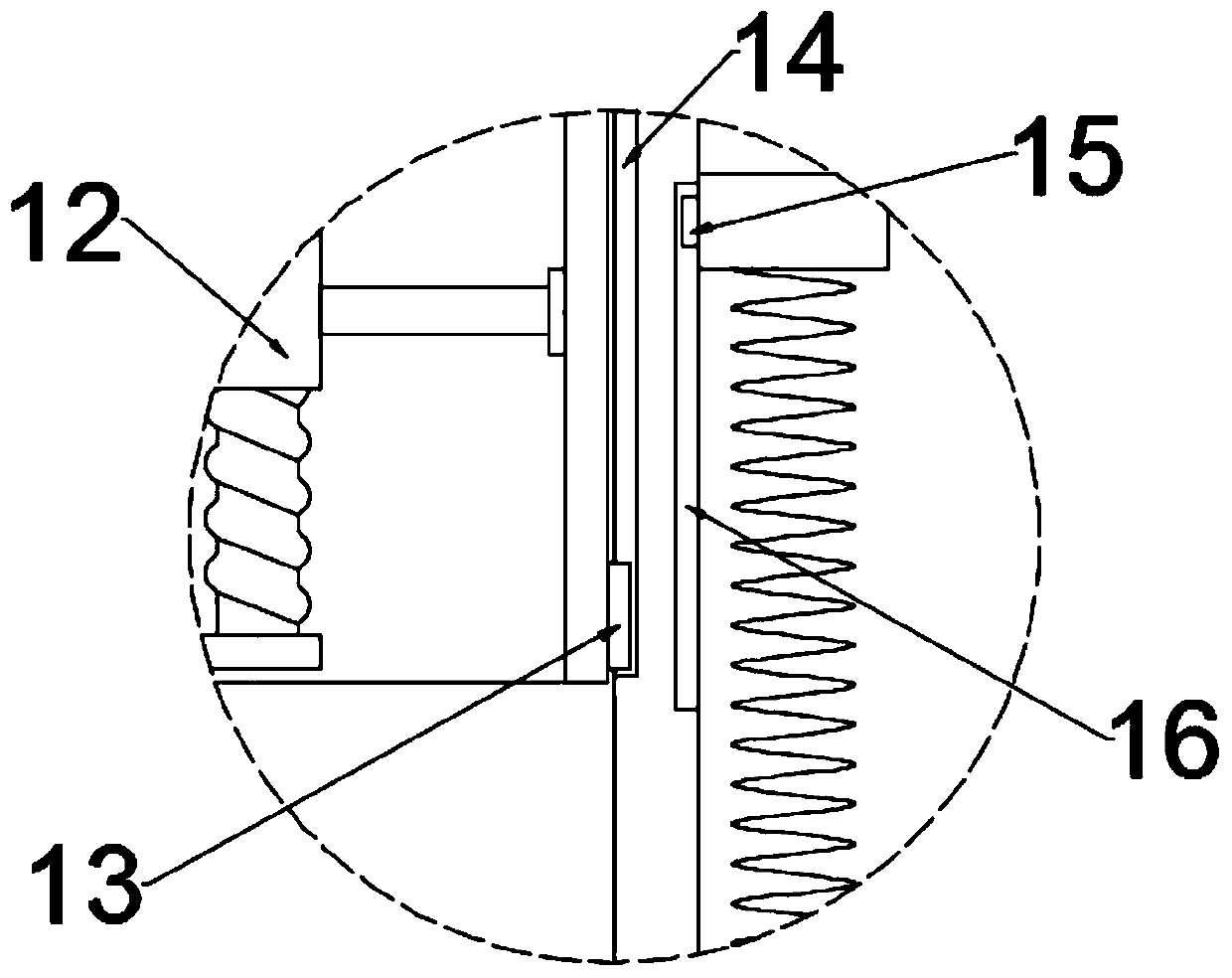
[0023] see Figure 1~3 , in an embodiment of the present invention, a pressure relief structure for a pressure cooker includes an upper cover 1 and a movable sleeve 4; the upper end of the movable sleeve 4 is fixedly connected with the upper cover 1, and the upper end of the side wall of the movable sleeve 4 At least one through hole 3 is provided, and the through hole 3 communicates with the inner and outer sides of the movable sleeve 4, and the inner side of the movable sleeve 4 is slidably installed with an adjusting sleeve 10 driven by an adjusting assembly, and the adjusting assembly is used for adjusting the sleeve 10 Adjust the position of the through hole 3 to change the passage area of ​​the through hole 3, so as to realize the adjustment according to different needs when the pressure cooker releases pressure, which is convenient to use and has a wide range of applications.

[0024] It should be noted that the horizontal cross-sectional area of ​​the upper cover 1 is lar

Embodiment 2

[0029] In the embodiment of the present invention, a pressure cooker cover is also proposed, which includes the cover 17 and the pressure relief structure for the pressure cooker described in the above embodiments.

[0030] Specifically, a rubber pad 18 is provided on the inner extension of the lower end of the pot cover 17, and the rubber pad 18 is used to abut against the upper edge of the pot body, thereby improving the sealing performance of the pot cover 17 after contacting the pot body. At least three locking buckles 19 are arranged on the inner side of the lower end extension of the cover 17. The thickness of one end of the locking buckle 19 is smaller than the thickness of the other end. 17 tightness connected with the pot body.

Embodiment 3

[0032] In the embodiment of the present invention, a pressure cooker is also proposed, including the pressure relief structure for the pressure cooker described in the above embodiment.


PUM


Abstract

The invention relates to the technical field related to pressure relief, in particular to a pressure relief structure for a pressure cooker, a pressure cooker cover and the pressure cooker. The pressure relief structure comprises an upper cover and a movable sleeve; the upper end of the movable sleeve is fixedly connected with the upper cover, at least one through hole is formed in the upper end of the side wall of the movable sleeve, the through holes are communicated with the inner side and the outer side of the movable sleeve, an adjusting sleeve driven by an adjusting assembly is slidablyinstalled on the inner side of the movable sleeve, and the adjusting assembly is used for adjusting the position of the adjusting sleeve to change the passage area of the through holes. The pressure relief structure is novel in design; through a knob, a threaded rod is driven by an adjusting rod to rotate, when the threaded rod rotates, the vertical position of the adjusting sleeve is driven to beadjusted under the action of the threaded sleeve and fixing rods, and thus the passage area of the through holes is changed; in pressure relief of the pressure cooker, adjustment can be carried out according to different needs, use is convenient, and the application range is wide.

Description


Claims


Application Information

Patent Timeline
Owner 武义伟诺工贸有限公司
Why Eureka
Try Eureka