DC transformer based on centralized multi-winding high-frequency transformer, and control method

A technology of DC transformers and high-frequency transformers, applied in the direction of converting DC power input to DC power output, control/regulation systems, instruments, etc., can solve the difficulty of further improving the power density of DC transformers, and the increase in the number of switching devices and high-frequency transformers, etc. question

Active Publication Date: 2019-08-23
SOUTHEAST UNIV
View PDF6 Cites 6 Cited by
  • Summary
  • Abstract
  • Description
  • Claims
  • Application Information

AI Technical Summary

Problems solved by technology

Furthermore, the number of switching devices and high-frequency transformers is also greatly

Method used


Image

  • DC transformer based on centralized multi-winding high-frequency transformer, and control method
  • DC transformer based on centralized multi-winding high-frequency transformer, and control method
  • DC transformer based on centralized multi-winding high-frequency transformer, and control method

Examples


Embodiment Construction

[0027] The technical solution of the present invention will be further described below in conjunction with the accompanying drawings and specific implementation examples.

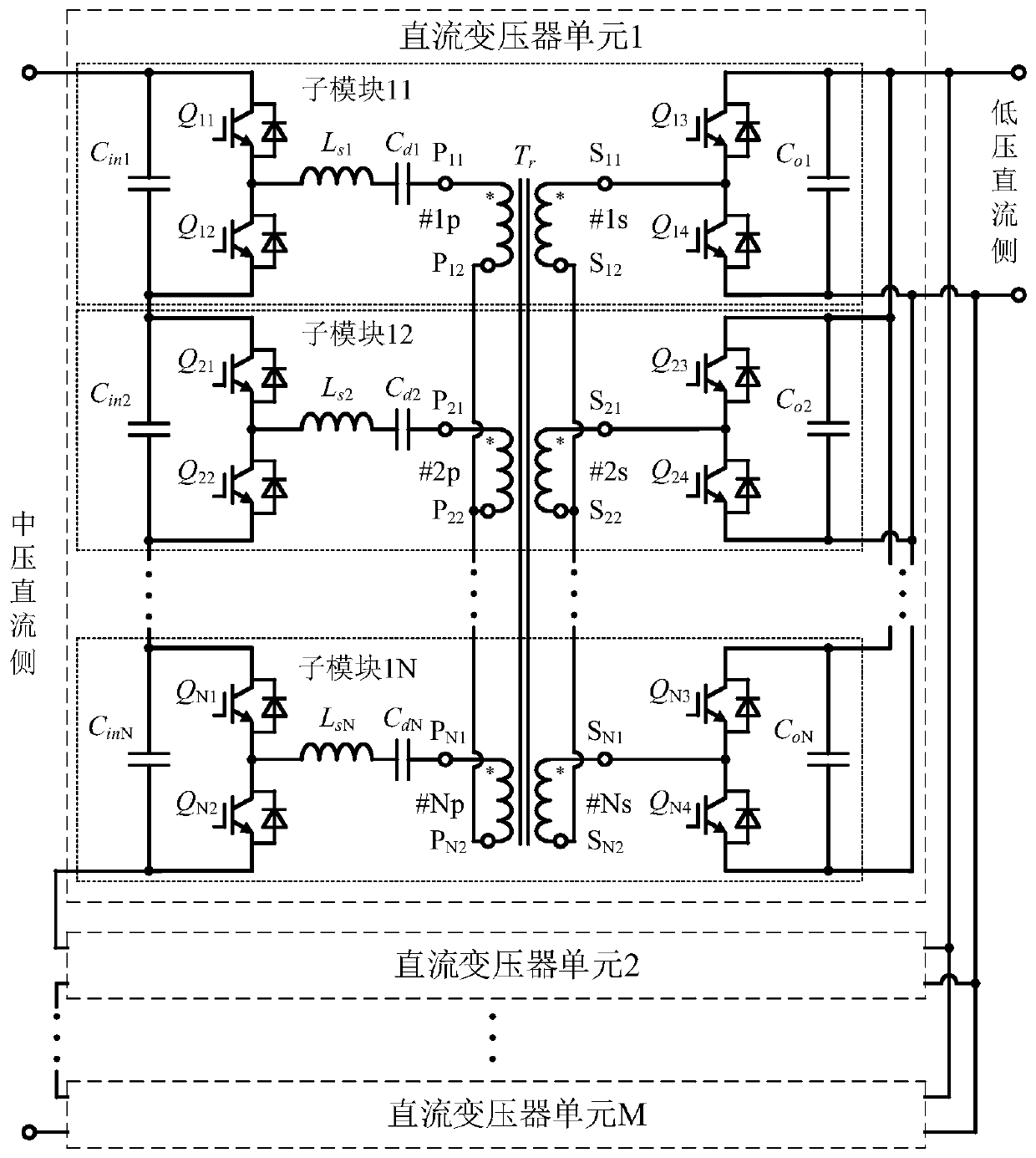
[0028] The invention designs a DC transformer based on a centralized multi-winding high-frequency transformer. Such as figure 1 As shown, the DC transformer topology is composed of M DC transformer units with input in series and output in parallel (ISOP), and each DC transformer unit contains N (N≥3) sub-modules with input in series and output in parallel. Contains an input filter capacitor C on the MV DC side ini , a bridge arm consisting of two switching tubes connected in series, and a transmission inductance L si , a DC blocking capacitor C di with the primary winding of the transformer. Contains an output filter capacitor C on the low voltage DC side oi , a bridge arm composed of two switch tubes in series and the secondary winding of the transformer.

[0029] In the i-th sub-module of the j-th DC t


PUM


Abstract

The invention discloses a DC transformer based on a centralized multi-winding high-frequency transformer, and a control method of the direct-current transformer. The transformer comprises M DC transformer units with input ends connected in series and output ends connected in parallel, wherein the medium-voltage DC side input ports of the M DC transformer units are connected in series to form a medium-voltage DC side port of the DC transformer, and low-voltage DC side output ports of the M DC transformer units are connected in parallel to form a low-voltage DC side port of the DC transformer. The multi-winding high-frequency transformers among the DC transformer units are mutually independent; each DC transformer unit comprises N submodules, the inputs of which are connected in series and the outputs of which are connected in parallel, wherein N is greater than or equal to 3; the input filter capacitors Cini of the submodules are connected in series to form a medium-voltage DC side input port of the unit, and the output filter capacitors Coi are connected in parallel to form a low-voltage DC side output port of the unit. According to the transformer, the bidirectional transmission of power between the medium-voltage DC side and the low-voltage DC side can be realized by controlling a phase shift angle between primary and secondary side bridge arms of the transformer in each sub-module, and zero-voltage switching-on of all switch tubes is realized.

Description


Claims


Application Information

Patent Timeline
Owner SOUTHEAST UNIV
Why Eureka
Try Eureka