Microwave power amplifier capable of realizing polarization mode selection

A microwave power and polarization technology, applied in amplifiers, amplifiers with semiconductor devices/discharge tubes, antennas, etc., can solve problems such as reducing system efficiency, and achieve the effect of low multi-polarization selection and low cost

Active Publication Date: 2022-07-29
SOUTHWEST CHINA RES INST OF ELECTRONICS EQUIP
View PDF9 Cites 0 Cited by
  • Summary
  • Abstract
  • Description
  • Claims
  • Application Information

AI Technical Summary

Benefits of technology

This patented technology allows for selective operation on different types of waves called linear or circular ones depending upon their orientation relative to an axis perpendicular to it's direction of propagation (X). By adjusting these modules based on how they generate electromagnetic radiation with specific frequencies, this device becomes able to efficiently transmit radio frequency energy over multiple modes simultaneously without wasting excessively more than necessary.

Problems solved by technology

Technological Problem: The current solution involves changing both horizontal and verbal polarizations simultaneously through multiple channels while maintaining good linearity (linear) performance. However, there may exist some cases where certain types of polarizers don't work well due to changes in their properties such as frequency response characteristics or impedance mismatches caused by factors like temperature variations. Additionally, if different polarizators were added separately during operation, they could cause interference between them which affects the quality of the final product.

Method used


Image

  • Microwave power amplifier capable of realizing polarization mode selection
  • Microwave power amplifier capable of realizing polarization mode selection
  • Microwave power amplifier capable of realizing polarization mode selection

Examples


specific example

[0049] For ease of understanding, this embodiment provides a specific example of a microwave power amplifier that can realize polarization mode selection, as follows:

[0050] In this embodiment, a power amplifier that realizes polarization mode selection through an electric bridge and a low-power phase shifter is provided, and the specific principle is described as follows:

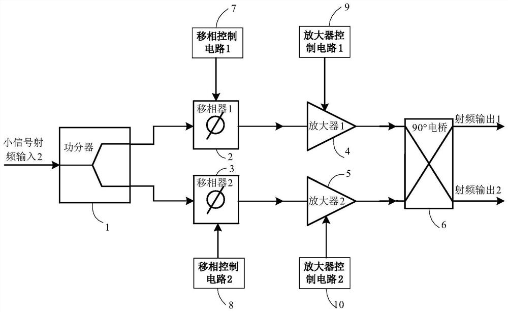
[0051] like figure 1 As shown, the power amplifier circuit mainly includes: a power divider (1), a phase shifter 1 (2), a phase shifter 2 (3), an amplifier 1 (4), an amplifier 2 (5), a 90° bridge (6 ), a phase-shift control circuit 1 (7), a phase-shift control circuit 2 (8), an amplifier control circuit 1 (9), and an amplifier control circuit 2 (10).

[0052] One output of the bridge is sent to the horizontally polarized antenna, and the other is output to the vertically polarized antenna. When only one end of the bridge connected to the horizontally polarized antenna has power output, the system outputs


PUM


Abstract

The invention discloses a microwave power amplifier capable of realizing polarization mode selection, which comprises a power divider, a first amplification branch consisting of a first phase shift control module and a first amplifier module, a second amplification branch consisting of a second phase shift control module and a second amplifier module, and a 90-degree bridge, a first signal and a second signal which are respectively generated by the power divider output to the first amplification branch and the second amplification branch are input to the 90-degree bridge, and radio frequency signal output is carried out by the horizontal polarized antenna and the vertical polarized antenna which are connected with the 90-degree bridge. The working states of the first amplifier module and the second amplifier module are controlled by controlling the phase shift quantity output of the first phase shift control module and the second phase shift control module, so that output control of circularly polarized waves, horizontal polarization, vertical polarization, linear polarization, left-hand circular polarization and right-hand circular polarization is realized, low-cost multi-polarization selection is realized, and the multi-polarization selection is realized. The problem of power loss during horizontal polarization and vertical polarization is solved.

Description


Claims


Application Information

Patent Timeline
Owner SOUTHWEST CHINA RES INST OF ELECTRONICS EQUIP
Why Eureka
Try Eureka