Equipment special for valve rod slot-position chamfering processing

A special equipment and cylinder technology, which is used in the field of special equipment for chamfering of valve cylinder grooves, can solve the problems of uneven chamfering, uneven chamfering, and inability to process, and achieves improved accuracy, good safety, and excellent performance. Effect

Pending Publication Date: 2019-09-03
GUANGDONG HENGBAO IND
View PDF0 Cites 2 Cited by
  • Summary
  • Abstract
  • Description
  • Claims
  • Application Information

AI Technical Summary

Benefits of technology

This patented technology allows for precise placement of valves during manufacturing processes without damaging their surface quality or causing damage from excessive force applied thereto. It uses an apparatus called a clamper system where two threadedly connected parts hold both ends of a rod-like member used to move the slab along its length. By controllably rotating one part around another, it controls how deep they go deeper into different positions inside the material being processed. A scanning device then moves upwardly towards each end of this process to measure any imperfections found within these spaces. Overall, this technology simplifies the way valve components are placed onto production lines while maintaining high levels of precision and efficiency.

Problems solved by technology

This patented technical problem addressed by this patents relates to improving the quality and precision required during part production processes such as machining or casting without damaging them due to imperfections like chipping on surfaces that may be present at certain points along the surface being worked upon.

Method used


Image

  • Equipment special for valve rod slot-position chamfering processing
  • Equipment special for valve rod slot-position chamfering processing
  • Equipment special for valve rod slot-position chamfering processing

Examples


Embodiment

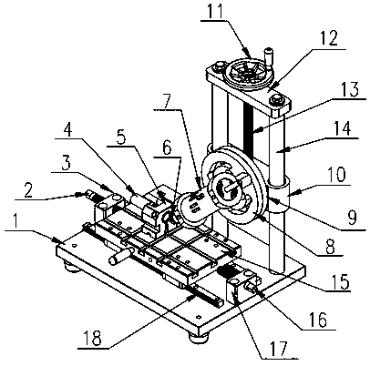
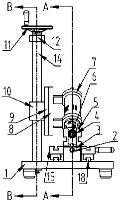
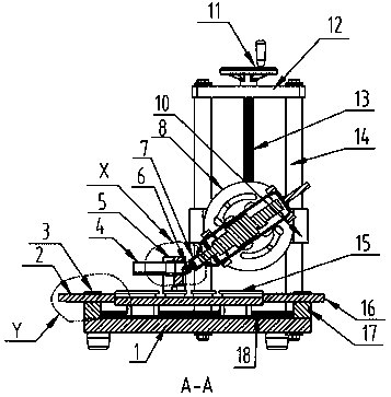
[0015] The structure diagram of the present invention is as figure 1 As shown, the special equipment for chamfering the groove position of the valve cylinder of the present invention includes a base plate 1, a left adjusting screw 2, a left limit block 3, a clamp body 5, a die head 6, an electric head 7, an adjustable turntable 8, Fixed plate 9, adjustable connecting plate 10, fixed horizontal plate 12, screw mandrel 13, column 14, clamp body bottom plate 15, right adjusting screw rod 16, right limit block 17, linear guide rail 18, wherein left limit block 3, right Limiting blocks 17 are respectively fixed on both sides of base plate 1, linear guide rail 18 is fixed on base plate 1, and left adjusting screw rod 2 and right adjusting screw rod 16 are respectively installed on the threads set by left limiting block 3 and right limiting block 17. The screw transmission pair is formed, the bottom plate 15 of the clamp body is installed on the linear guide rail 18, the clamp body 5 is


PUM


Abstract

The invention relates to equipment special for valve rod slot-position chamfering processing. The equipment comprises a baseplate, an electric head, an adjustable rotation disc, a fixing disc, an adjustable connection plate, a linear guide rail and the like. A left limit block and a right limit block are fixed to the two sides of the baseplate respectively, the linear guide rail is fixed to the baseplate, a left adjustment screw and the left limit block from a spiral transmission pair, and a right adjustment screw and the right limit block from a spiral transmission pair; a clamp body baseplate is installed on the linear guide rail, a clamp body is installed on the clamp body baseplate, and columns are fixed to one side of the baseplate; a fixing horizontal plate is installed at the tops of the columns, and the adjustable connection plate is arranged on the columns; one end of a lead screw penetrates through a thread arranged on the adjustable connection plate to form a spiral transmission pair, and the other end of the lead screw penetrates through a through hole formed in the fixing horizontal plate and extends out of the fixing horizontal plate; the fixing disc is fixedly installed on the adjustable connection plate, the adjustable rotation disc is installed on the fixing disc, the electric head is installed on the adjustable rotation disc, and an output shaft of the electric head is connected with a die head. According to the equipment, the problem is solved that valve rod slot-position chamfering processing is difficult.

Description


Claims


Application Information

Patent Timeline
Owner GUANGDONG HENGBAO IND
Why Eureka
Try Eureka