High-pressure pump

A technology for high-pressure pumps and fuel oil, applied in pump components, fuel injection pumps, fuel injection devices, etc., can solve problems such as increasing the volume of high-pressure pumps, and achieve the effect of small space

Active Publication Date: 2019-09-03
纬湃汽车电子(长春)有限公司
View PDF8 Cites 1 Cited by
  • Summary
  • Abstract
  • Description
  • Claims
  • Application Information

AI Technical Summary

Benefits of technology

This new type of hydraulic system uses an impeller with two channels that are separated from each other at one end called the back pressure chamber (BP). To reduce its size it suggests placing dampers near certain parts or areas where there can be problems during operation.

Problems solved by technology

High Pressure Pumps are commonly found on vehicles that use diesel fuels for powering their engines or other systems such as air conditioners (Air Conditioned Heat Exchangers) due to its ability to provide stable hydraulic fluid under specific conditions during operation. However, this technology also produces harmful noises from fluctuations caused by changes made over time. To address these issues, there has been developed an improved design called dampener system.

Method used


Image

  • High-pressure pump
  • High-pressure pump
  • High-pressure pump

Examples


Embodiment Construction

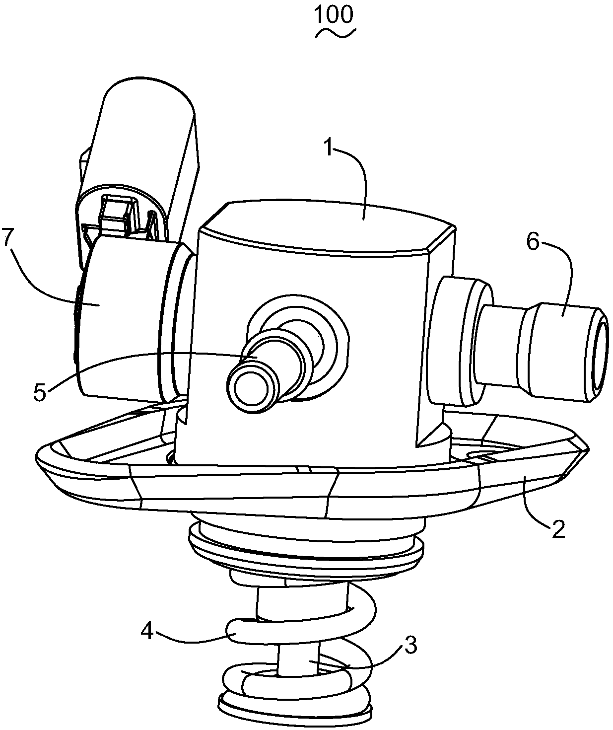
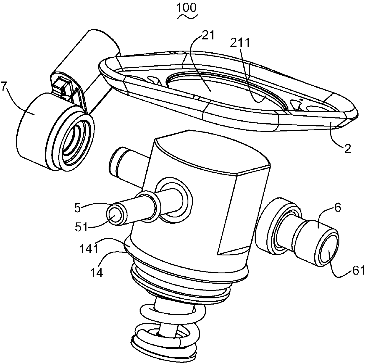
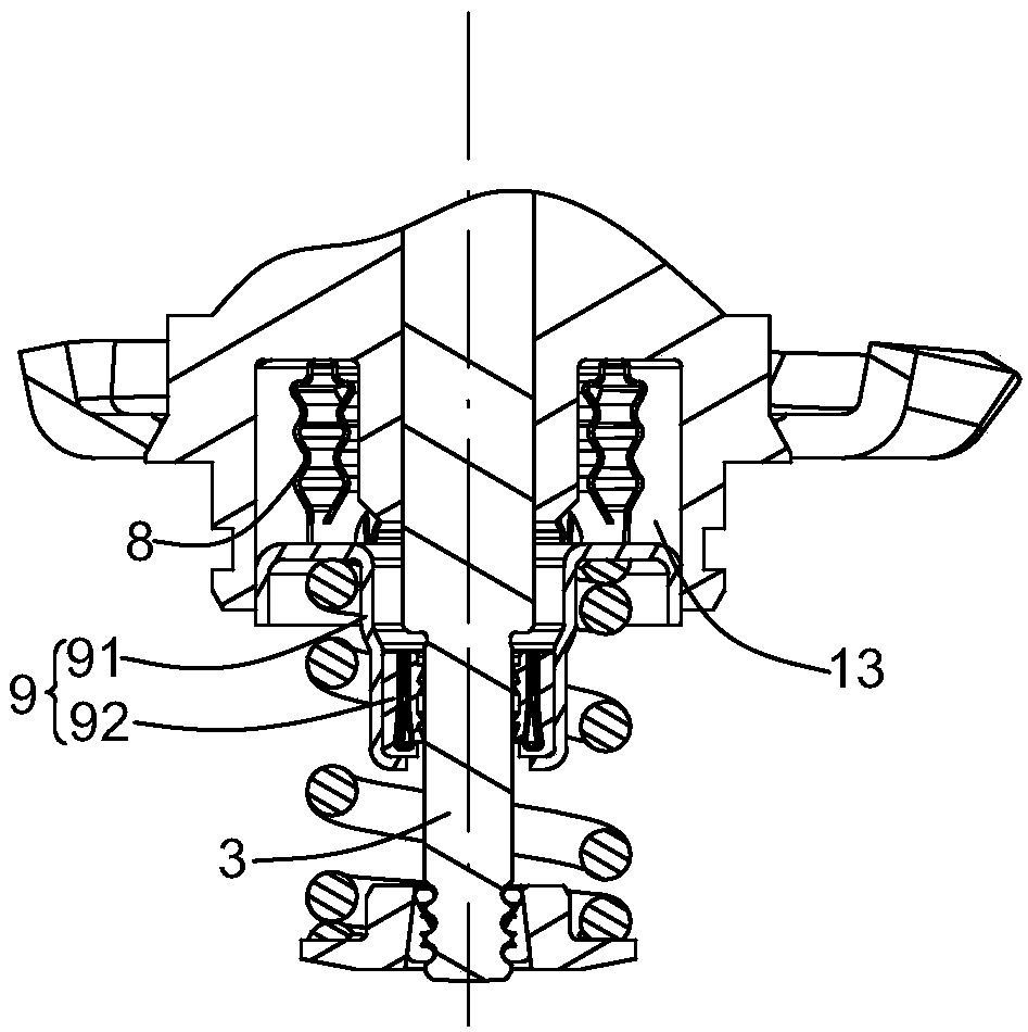
[0024] see Figure 1 to Figure 5 As shown, the present invention provides a high-pressure pump 100, which includes a housing 1, a plunger 3, a fixing member 2, a spring 4, a fuel inlet port 5, a fuel outlet port 6, a solenoid valve control port 7, a damper 8 and a seal Holder 9. The fuel inlet port 5 is provided with a fuel inlet channel 51 , and the fuel outlet port 6 is provided with a fuel outlet channel 61 . A fuel inlet port 5 and a fuel outlet port 6 are fixed to the housing 1 .

[0025] The housing 1 is provided with a central axis L. As shown in FIG. The housing 1 includes a plunger channel 12 , a plunger cavity 11 connected to the plunger channel 12 and a protruding portion 14 extending outward. The protruding portion 14 has a first mating surface 141 . The housing 1 also includes a buffer chamber 13 arranged around the plunger passage 12 and a connecting passage 14 connecting the buffer chamber 13 with the fuel inlet passage 51 . The damper 8 is fixed in the buffer


PUM


Abstract

The invention provides a high-pressure pump. The high-pressure pump comprises a fuel inlet end provided with a fuel inlet channel, a fuel outlet end provided with a fuel outlet channel, a shell, a plunger and a damper, wherein the shell is provided with a central shaft, and the fuel inlet end and the fuel outlet end are fixed to the shell; the shell comprises a plunger channel, a plunger cavity connected with the plunger channel, a buffer chamber arranged at the periphery of the plunger channel and a connecting passage communicating the buffer chamber with the fuel inlet channel; the plunger is arranged in the plunger channel and does reciprocating motion in the plunger channel in the central shaft direction; and the damper is fixed in the buffer chamber. According to the pump, the damperis fixed in the buffer chamber arranged at the periphery of the plunger channel, so that the space occupied by the high-pressure pump is reduced.

Description


Claims


Application Information

Patent Timeline
Owner 纬湃汽车电子(长春)有限公司
Why Eureka
Try Eureka