Sewage collection device and sewage treatment system

A sewage treatment system and sewage collection technology, applied in the direction of filtration and separation, fixed filter elements, chemical instruments and methods, etc., can solve the problems of inconvenient cleaning of banded waste, increased difficulty of construction, and inability to clean sludge, etc. It achieves the effect of easy handling, large range and high waste cleaning efficiency

Inactive Publication Date: 2019-09-20
CHANGSHA QIUDIANBING INFORMATION TECH CO LTD
View PDF6 Cites 2 Cited by
  • Summary
  • Abstract
  • Description
  • Claims
  • Application Information

AI Technical Summary

Benefits of technology

This patented technology describes an apparatus for collecting and treating water pollution caused by various sources such as domestic or industrial wastes. A deep cleanser mechanism is included along one side of the machine's housing where the waste can come downward when being treated. An accumulation box stores the soil removed by the cleaner assembly. By moving them closer together within the tank body, they become compact and efficient. Additionally, the apparatus includes a thread connection for easy maintenance purposes due to ease of movement. Overall, this design allows for effective management of contaminated waters without causing problems like leakages and damaging equipment.

Problems solved by technology

This technical problem addressed by this patented technology relates to improving the design for sewer systems with high pressure water jets or other tools such as wire brushers to remove sediment buildup on pipe walls during maintenance operations without causing damage.

Method used


Image

  • Sewage collection device and sewage treatment system
  • Sewage collection device and sewage treatment system
  • Sewage collection device and sewage treatment system

Examples


Embodiment Construction

[0025] In order to make the technical means, creative features, goals and effects achieved by the present invention easy to understand, the present invention will be further described below in conjunction with specific embodiments.

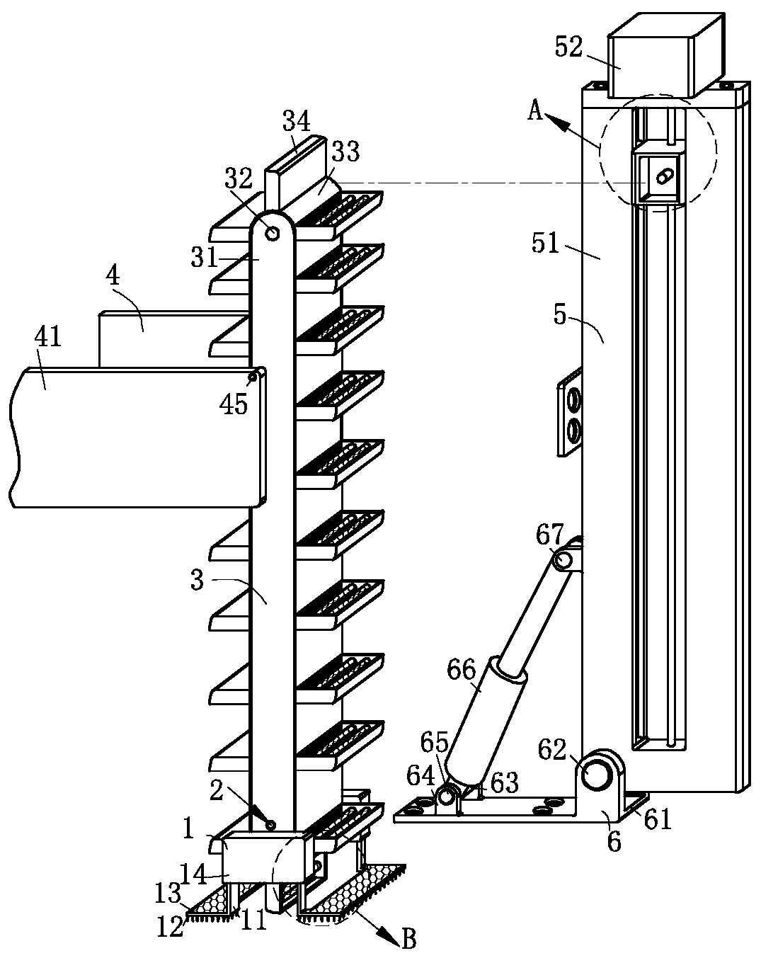
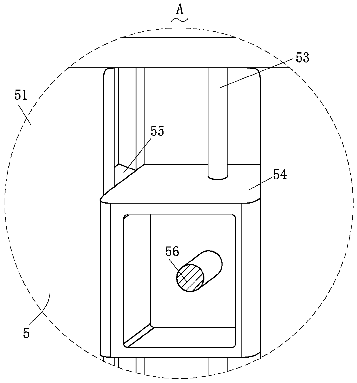
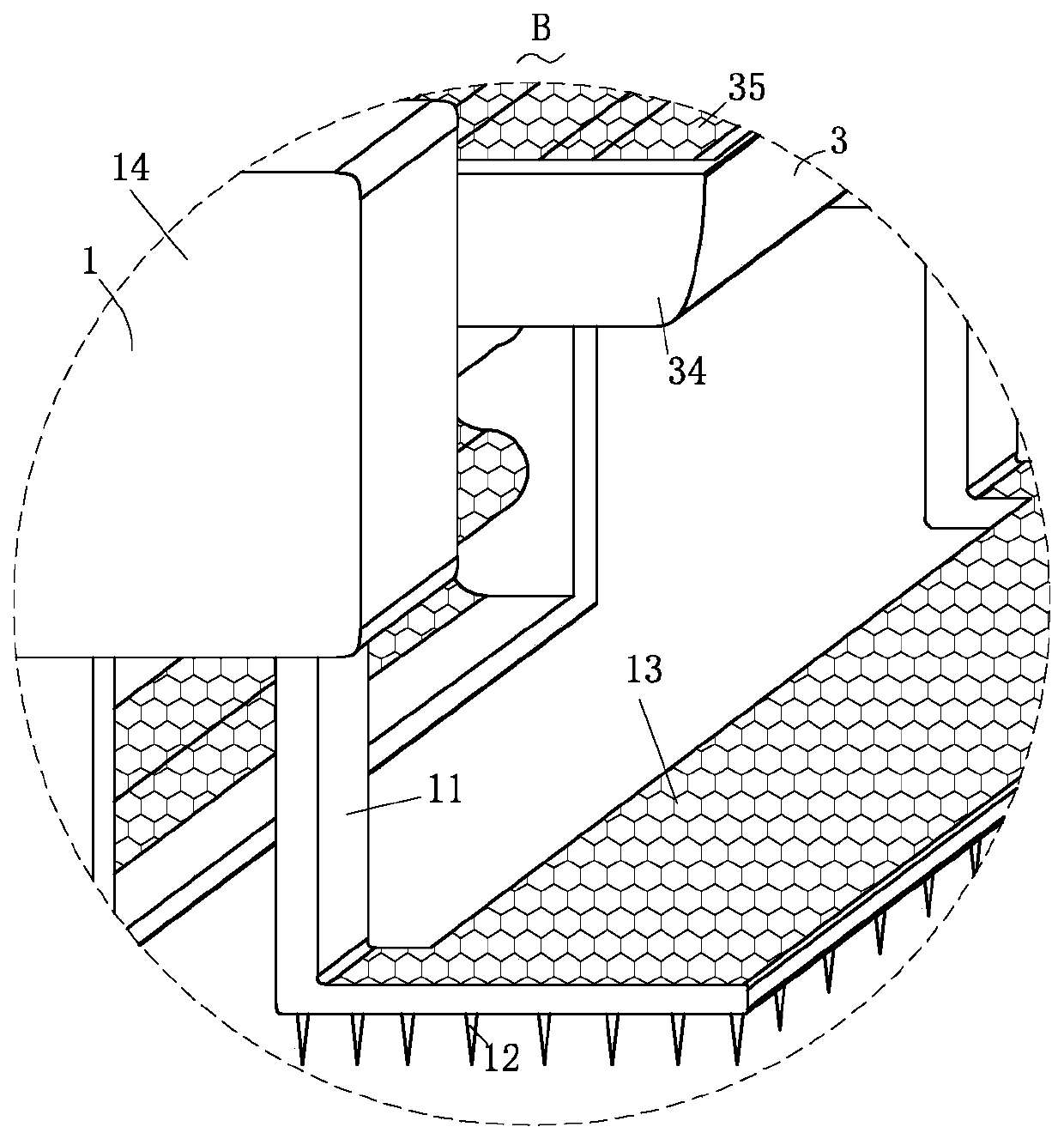
[0026] Such as Figure 1-Figure 6 As shown, a sewage collection device and a sewage treatment system according to the present invention include a dredging structure 1, a drainage hole 2, a waste cleaning structure 3, a storage structure 4, a depth adjustment structure 5 and an angle adjustment structure 6; The angle adjustment structure 6 of the angle is connected to the depth adjustment structure 5 for adjusting the depth of sludge cleaning, and the angle adjustment structure 6 is rotationally connected with the depth adjustment structure 5; on the angle adjustment structure 6 The waste debris cleaning structure 3 for receiving and filtering belt-shaped waste debris and its large particle waste debris is provided, and the waste debris cleaning struc


PUM


Abstract

The invention relates to the field of sewage collection devices and sewage treatment systems, concretely to a sewage collection device and a sewage treatment system. The sewage collection device includes a dredging structure, a drain hole, a debris cleaning structure, a storage structure, a depth adjustment structure and an angle adjustment structure. The debris cleaning structure is arranged on the depth adjustment structure. The debris cleaning structure is slidingly connected to the depth adjustment structure, which facilitates the adjustment of the depth of the debris cleaning structure into a sewage well so as to facilitate the layer-by-layer cleaning of sewage and debris in the sewage well, which facilitates the utilization of the device in sewage wells with different depth, thereby greatly improving the operation flexibility. The debris cleaning structure is fixed to the depth adjustment structure so as to facilitate the separation of the sewage and the debris to effectively prevent a silt pump from blockage and damage and facilitate the removal of the debris in sewage well out of the sewage well, thereby greatly improving the classification efficiency and quality of the sewage and the debris and further reducing the construction difficulty.

Description


Claims


Application Information

Patent Timeline
Owner CHANGSHA QIUDIANBING INFORMATION TECH CO LTD
Why Eureka
Try Eureka