Heat exchanger design method and device, storage medium and electronic equipment

A heat exchanger and heat exchange technology, applied in the field of device, heat exchanger design, storage medium and electronic equipment, can solve problems such as low design efficiency, reduce workload, improve design efficiency, and shorten development cycle Effect

Active Publication Date: 2019-12-20
GREE ELECTRIC APPLIANCES INC
View PDF10 Cites 1 Cited by
  • Summary
  • Abstract
  • Description
  • Claims
  • Application Information

AI Technical Summary

Benefits of technology

The present technology allows for efficient use of heat transfer devices such as radiators or refrigeration systems used on vehicles (refrigerated cars). By fitting specifications into these heat exchanges based upon their dimensions and properties, they can achieve better performance without requiring excessive effort. Additionally, this approach simplifies the process of developing new equipment while reducing its complexity.

Problems solved by technology

The technical problem addressed in this patented text relates to improving the performance of heat-exchange systems used with air conditioning units (ACUs). Current designs require significant effort from engineers over time due to their complexity and lack of efficient methods that aim towards achieving better results through improved fluid paths or improvements made on existing structures.

Method used


Image

  • Heat exchanger design method and device, storage medium and electronic equipment
  • Heat exchanger design method and device, storage medium and electronic equipment
  • Heat exchanger design method and device, storage medium and electronic equipment

Examples


Embodiment Construction

[0060] In order to make the purpose, technical solution and advantages of the present application clearer, the technical solution of the present application will be described in detail below. Apparently, the described embodiments are only some of the embodiments of this application, not all of them. Based on the embodiments in the present application, all other implementation manners obtained by persons of ordinary skill in the art without creative efforts fall within the protection scope of the present application.

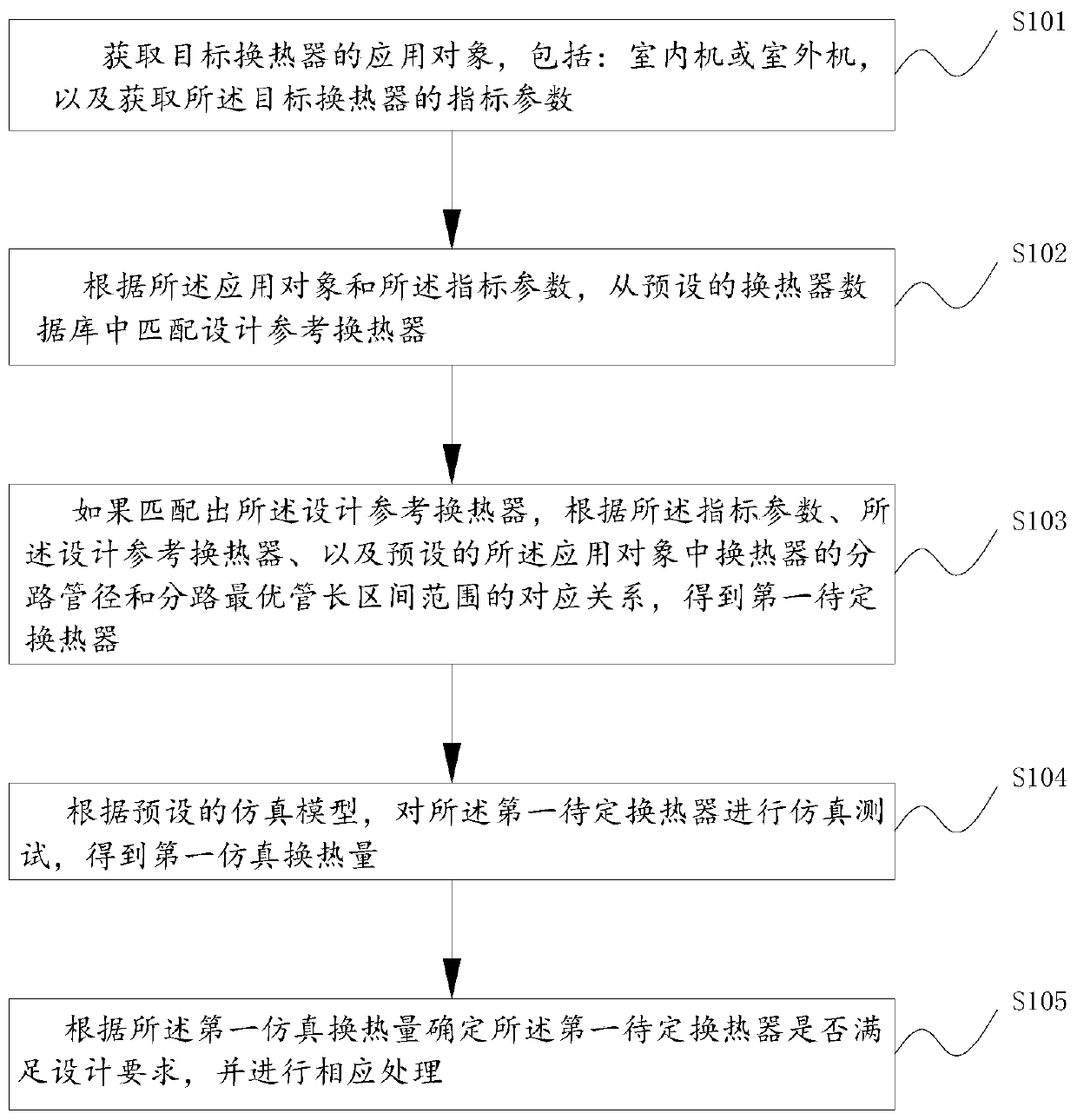
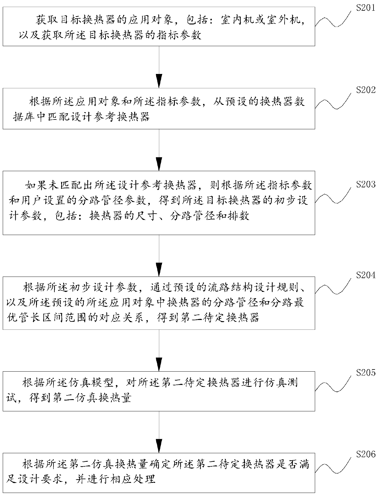
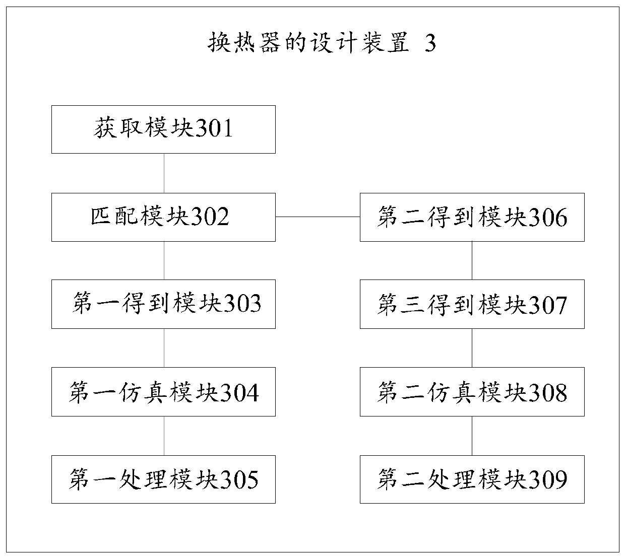
[0061] figure 1 A schematic flow diagram of a design method for a heat exchanger provided in an embodiment of the present application, such as figure 1 As shown, the design method of the heat exchanger includes the following steps:

[0062] Step S101, obtaining the application object of the target heat exchanger, including: indoor unit or outdoor unit, and obtaining the index parameters of the target heat exchanger;

[0063] Taking an air conditioner as an exampl


PUM


Abstract

The invention relates to a heat exchanger design method and device, a storage medium and electronic equipment, and belongs to the technical field of heat exchanger design. The heat exchanger design method comprises the steps: obtaining application objects, including an indoor unit or an outdoor unit, of a target heat exchanger, and obtaining index parameters of the target heat exchanger; matchingand designing a reference heat exchanger from a preset heat exchanger database according to the application object and the index parameters; if the designed reference heat exchanger is matched, obtaining a first undetermined heat exchanger according to the index parameters, the designed reference heat exchanger and the preset corresponding relation between the shunt pipe diameter of the heat exchanger in the application object and the shunt optimal pipe length interval range; according to a preset simulation model, performing a simulation test on the first to-be-determined heat exchanger to obtain a first simulation heat exchange amount; and determining whether the first to-be-determined heat exchanger meets the design requirement or not according to the first simulation heat exchange amount, and performing corresponding processing. Through the heat exchanger design method, design efficiency of the heat exchanger can be improved.

Description


Claims


Application Information

Patent Timeline
Owner GREE ELECTRIC APPLIANCES INC
Why Eureka
Try Eureka