Laser radar system based on one-dimensional diffractive optical element DOE

A technology of diffractive optical element and laser radar, which is applied in the field of laser radar system based on one-dimensional diffractive optical element DOE, which can solve the problem of poor ranging accuracy, low energy utilization rate of outgoing laser beam, and lower signal-to-noise ratio of laser radar system and other issues to achieve the effect of improving scanning efficiency and detection distance

Pending Publication Date: 2020-01-07
探维科技(北京)有限公司
View PDF11 Cites 6 Cited by
  • Summary
  • Abstract
  • Description
  • Claims
  • Application Information

AI Technical Summary

Problems solved by technology

[0003] The detection distance and ranging accuracy of lidar are mainly limited by light energy: the received light energy is not high and the light energy utilization rate of the outgoing laser beam is not high, resulting in a lower signal-to-noise ratio of the lidar system, a small detection distance, Problems such as poor ranging accuracy

Method used


Image

  • Laser radar system based on one-dimensional diffractive optical element DOE
  • Laser radar system based on one-dimensional diffractive optical element DOE
  • Laser radar system based on one-dimensional diffractive optical element DOE

Examples


Example Embodiment

[0035] Various exemplary embodiments, features, and aspects of the present disclosure will be described in detail below with reference to the drawings. The same reference numerals in the drawings indicate elements with the same or similar functions. Although various aspects of the embodiments are shown in the drawings, unless otherwise noted, the drawings are not necessarily drawn to scale.

[0036] The dedicated word "exemplary" here means "serving as an example, embodiment, or illustration." Any embodiment described herein as "exemplary" need not be construed as being superior or better than other embodiments.

[0037] In addition, in order to better illustrate the present disclosure, numerous specific details are given in the following specific embodiments. Those skilled in the art should understand that without certain specific details, the present disclosure can also be implemented. In some instances, the methods, means, elements, and circuits well-known to those skilled in th


PUM


Abstract

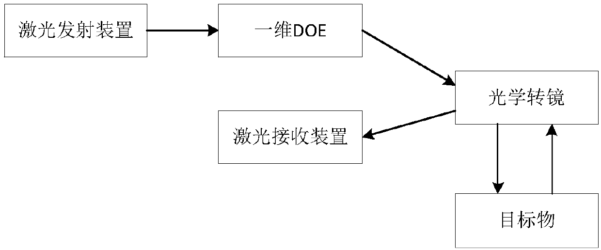
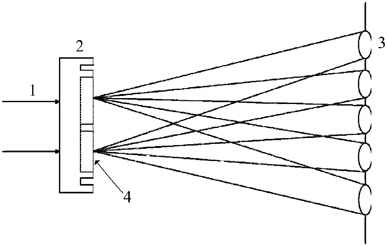
The disclosure relates to a laser radar system based on a one-dimensional diffractive optical element DOE, and the system comprises a laser emitting device, the one-dimensional DOE, an optical rotating mirror and a laser receiving device, wherein the laser emitting device is used for emitting a laser beam; the one-dimensional DOE is used for splitting the laser beam into one-dimensional lattice laser beams with uniform light intensity distribution; the optical rotating mirror is capable of rotating around a rotation axis, receiving the one-dimensional lattice laser beams, and adjusting the direction of the one-dimensional lattice laser beams in the rotating process and reflecting the one-dimensional lattice laser beams to the target; and the echo of the one-dimensional lattice laser beamsafter diffuse reflection on the target returns to the optical rotating mirror, and is received by the laser receiving device after being reflected by the optical rotating mirror. By setting the one-dimensional DOE, the laser beam passing through the one-dimensional DOE can be split into one-dimensional lattice laser beams with uniform light intensity distribution, so that the light energy is distributed at the required point in a concentrated manner. In this way, the laser energy is effectively used to improve the scanning efficiency and detection range of the laser radar system.

Description


Claims


Application Information

Patent Timeline
Owner 探维科技(北京)有限公司
Why Eureka
Try Eureka