Optical scanning device and image forming apparatus
- Summary
- Abstract
- Description
- Claims
- Application Information
AI Technical Summary
Benefits of technology
Problems solved by technology
Method used
Image

Examples
first embodiment
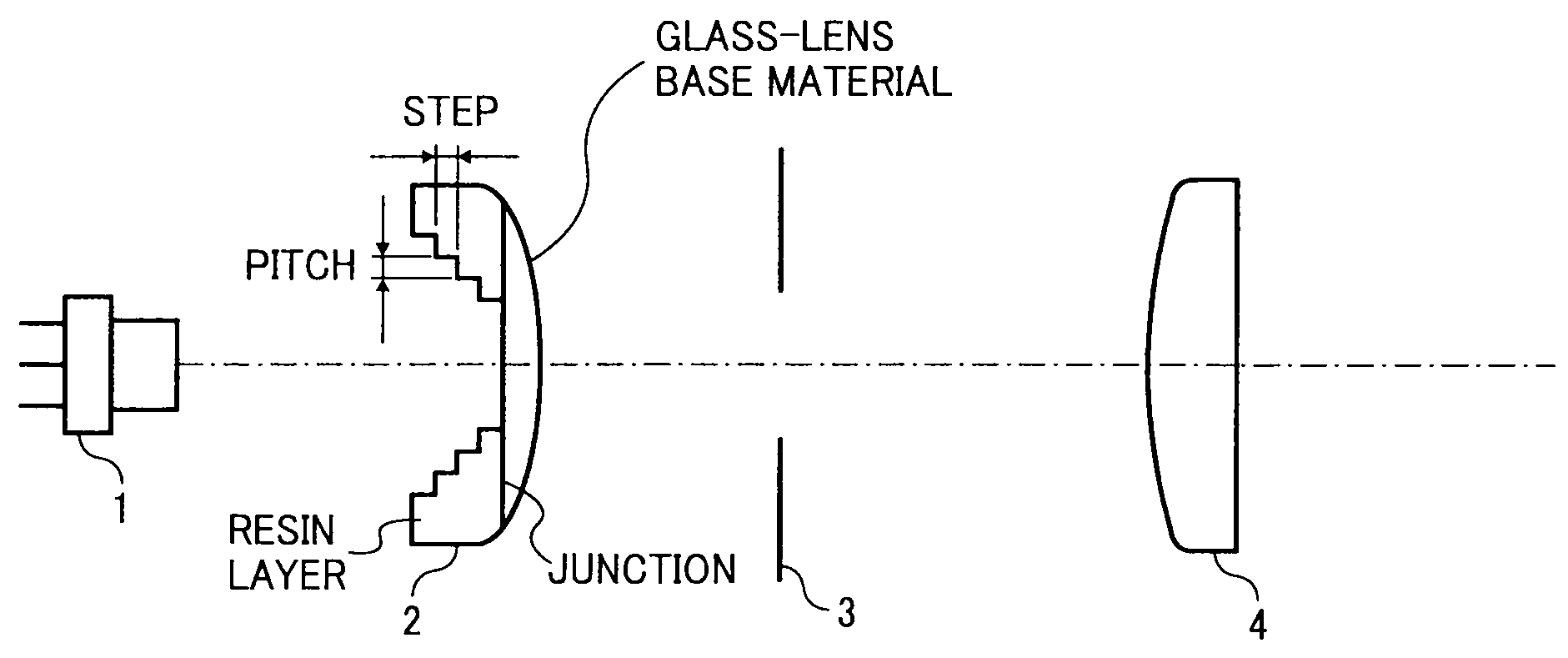
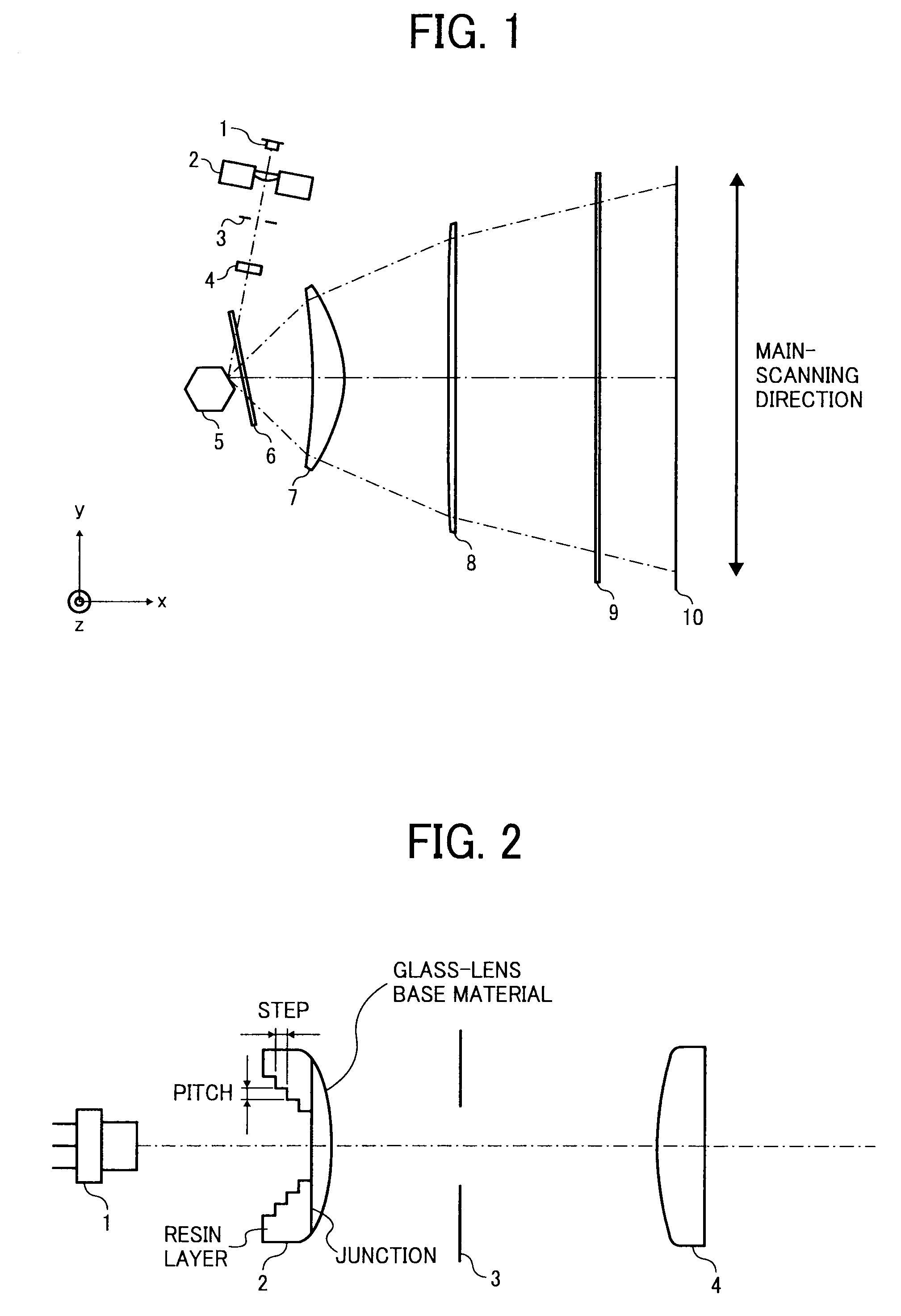
[0023]FIG. 1 represents an example of optical arrangement of an optical scanning device according to the present invention. The optical scanning device includes a laser diode (LD) 1 as a light source, a coupling lens 2, an aperture member 3, a linear-image forming lens 4, a rotating polygon mirror 5 as an optical deflector, a soundproof glass 6 as a window of a soundproof housing (not shown) that houses the polygon mirror 5, scanning optical members (scanning lenses) 7 and 8, and a dustproof glass 9 as a part of a housing that houses the optical system in FIG. 1 and prevents entry of dust into the housing. The optical scanning device scans a surface to be scanned 10.
[0024]A divergent light beam emitted from the laser diode 1 is converted into a substantially parallel light beam by the coupling lens 2. The parallel beam is beam-shaped by the aperture member 3 and then it is made to fall on the linear-image forming lens 4. The parallel light beam, after passing through the linear-image f
second embodiment
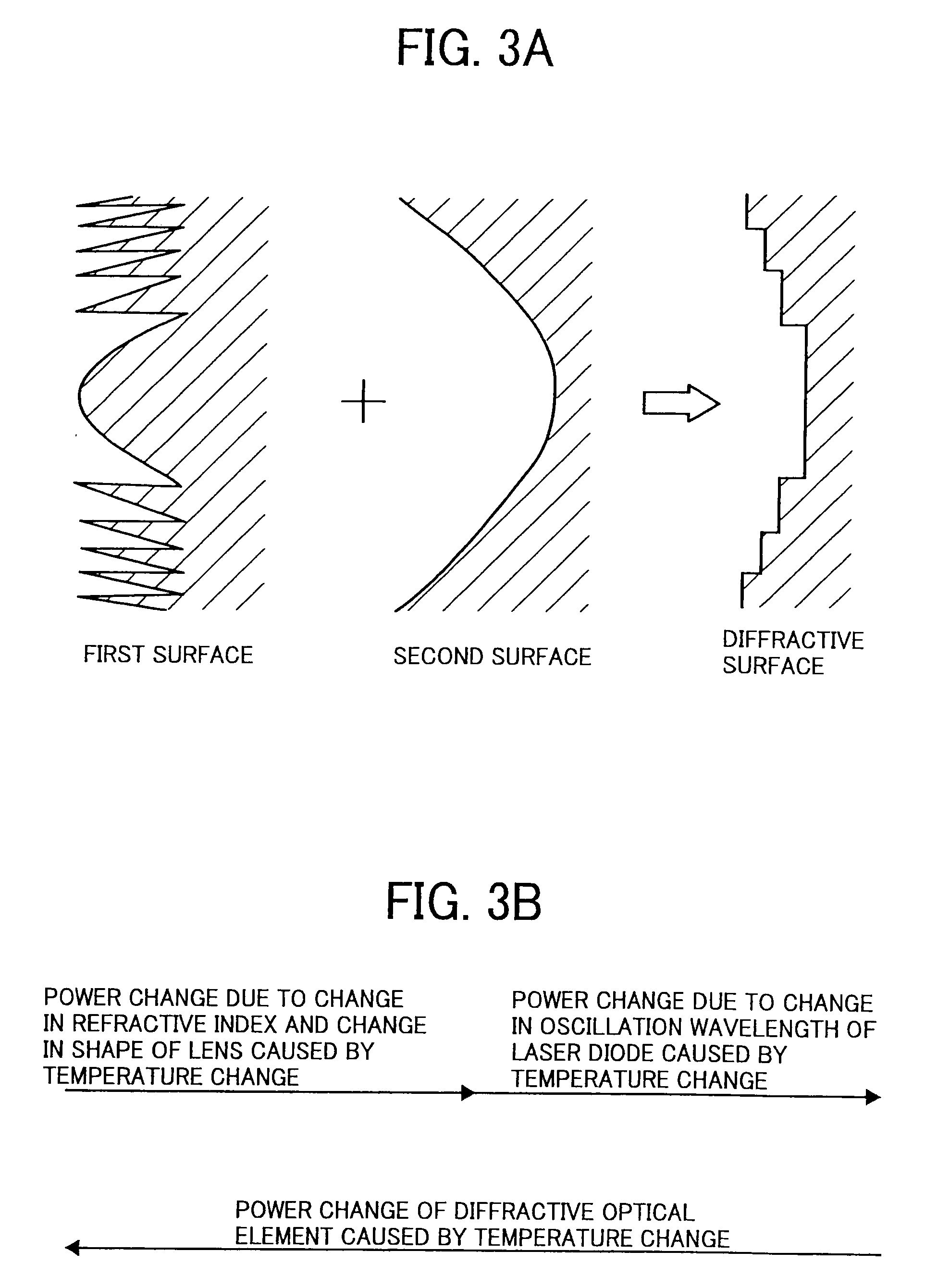
[0074]A refractive index of the lens, a shape of the lens, and an oscillation wavelength of the laser diode change as the temperature changes, which causes displacement in an image location. A second curvature radius (diffraction power) is designed so as to reduce the displacement. The scanning optical system used in an image forming apparatus is provided with an anamorphic optical system in which magnifications of the optical systems in a direction corresponding to the main-scanning direction and in a direction corresponding to the sub-scanning direction are different from each other. Therefore, if the displacement of the image location caused by the temperature change is corrected in the diffractive optical element, required diffraction power in a direction corresponding to the main-scanning direction is different from that in a direction corresponding to the sub-scanning direction.
[0075]FIG. 7A represents a relationship between a curvature radius of the second surface and the numbe
third embodiment
[0085]FIG. 8 is a schematic of an example of an image forming apparatus according to the present invention. The image forming apparatus is a tandem-type full-color optical printer. Provided in the lower part of the apparatus is a conveyor belt 17 for conveying a transfer paper (not shown) fed from a paper feeding cassette 13 that is placed in the horizontal direction. A photosensitive element 27Y for yellow, a photosensitive element 27M for magenta, a photosensitive element 27C for cyan, and a photosensitive element 27K for black are arranged at an equal space along the upper part of the conveyor belt 17 in this order from the upstream side. Hereafter, Y, M, C, and K in signs represent yellow, magenta, cyan, and black, respectively.
[0086]All the photosensitive elements 27Y, 27M, 27C, and 27K are formed so as to have the same diameter, and process units are sequentially arranged around each of the photosensitive elements according to electrophotographic process. Sequentially arranged ar
PUM
 Abstract
Description
Claims
Application Information
 - R&D Engineer
- R&D Manager
- IP Professional
- Industry Leading Data Capabilities
- Powerful AI technology
- Patent DNA Extraction
Browse by: Latest US Patents, China's latest patents, Technical Efficacy Thesaurus, Application Domain, Technology Topic.
© 2024 PatSnap. All rights reserved.Legal|Privacy policy|Modern Slavery Act Transparency Statement|Sitemap