Auxiliary fixing equipment for piglet injection
A technology for fixed equipment and young pigs, which is applied in veterinary equipment, medical science, equipment for restraining animals, etc. It can solve problems such as fixed, ineffective young pigs, and inability to guarantee personal safety, so as to reduce operating steps and reduce activity space Effect
- Summary
- Abstract
- Description
- Claims
- Application Information
AI Technical Summary
Benefits of technology
Problems solved by technology
Method used
Image

Examples
Embodiment 1
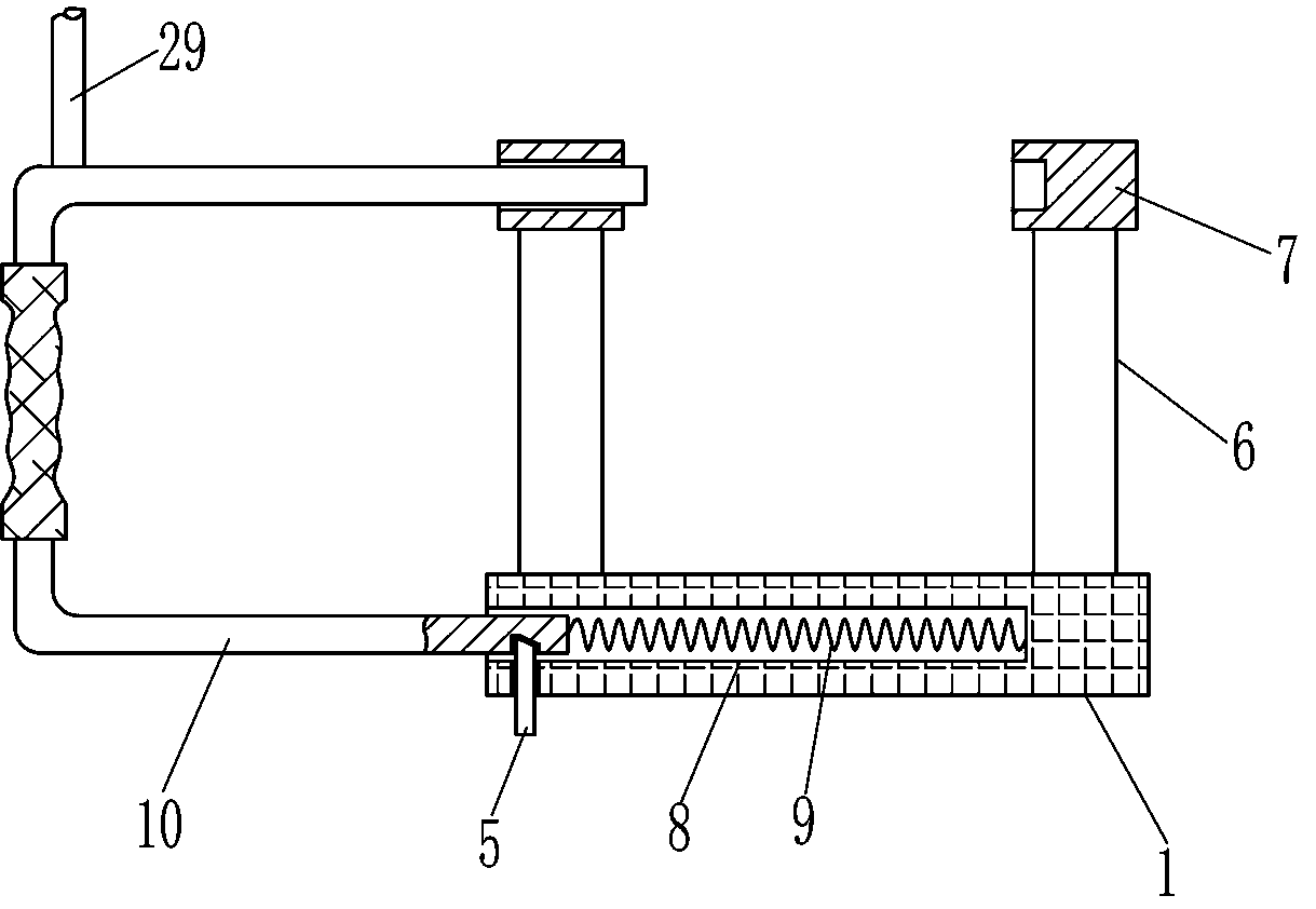
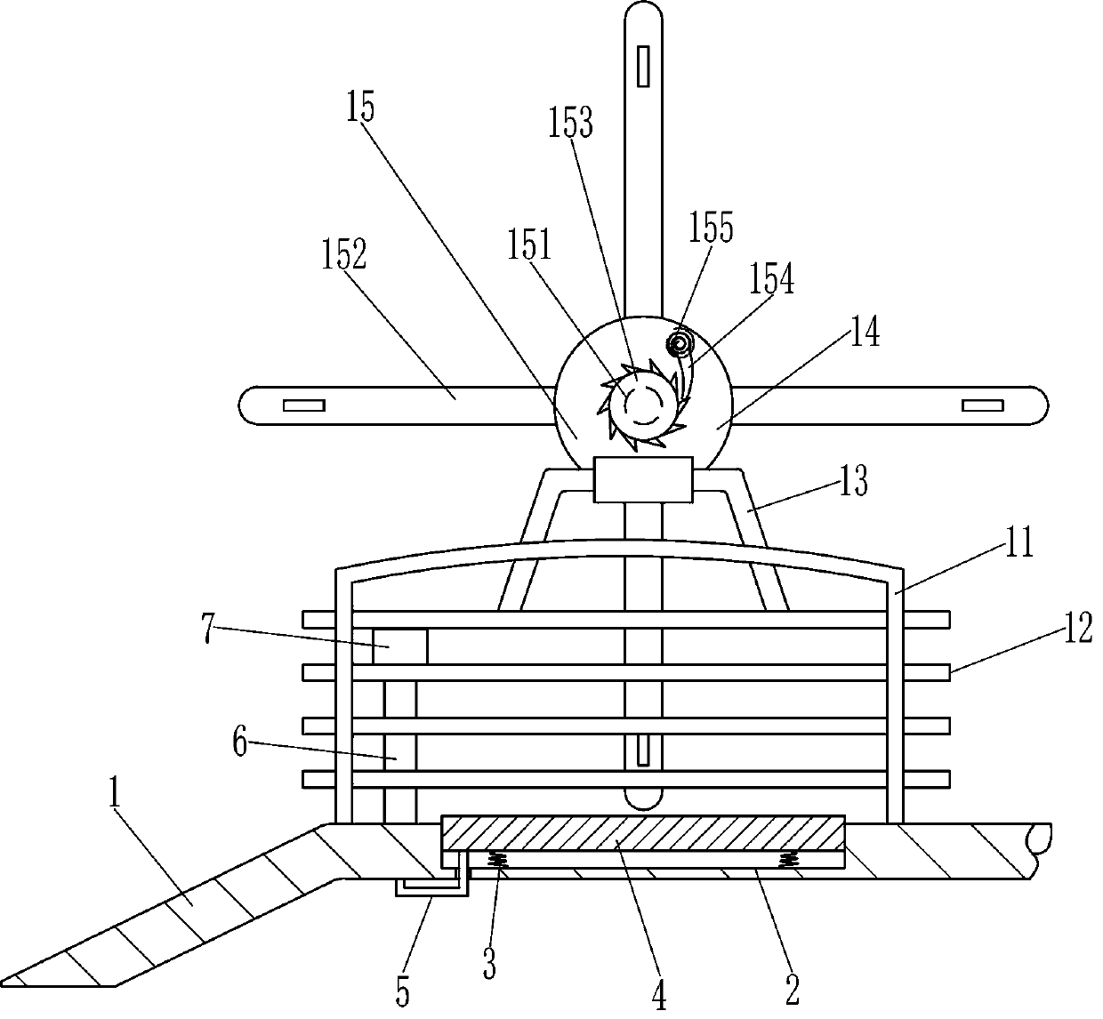
[0019] An auxiliary fixation device for injections of young pigs, such as Figure 1-3 As shown, it includes a mounting plate 1, a conical spring 3, a sliding plate 4, a U-shaped clamping rod 5, a supporting column 6, a ferrule 7, a first compression spring 9, a U-shaped pull rod 10, a mounting frame 11, and a cross bar 12 , a support base 13, a mounting plate 14 and a limit device 15, the top of the mounting plate 1 is provided with a sliding groove 2, the inner bottom of the sliding groove 2 is distributedly connected with a conical spring 3, and the sliding groove 2 is connected with a sliding plate 4 in a sliding manner. The bottom of the sliding plate 4 is fixedly connected to the top of the conical spring 3, and one side of the bottom of the sliding plate 4 is connected with a U-shaped clamping rod 5, and the U-shaped clamping rod 5 is slidingly connected with the mounting plate 1, and one side of the mounting plate 1 is symmetrically provided with supports. Column 6, ferrul
Embodiment 2
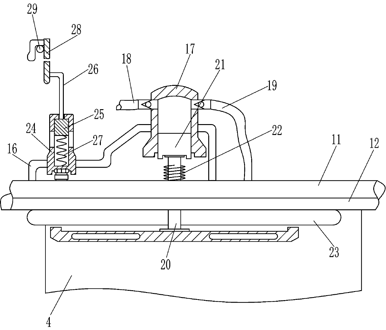
[0023] On the basis of Example 1, such as image 3 As shown, it also includes a support rod 16, a cylinder body 17, an intake pipe 18, an exhaust pipe 19, a push plate 20, a piston 21, a second compression spring 22, an air bag 23, an exhaust frame 24, a block 25, an L-shaped Pull bar 26 and the 3rd compression spring 27, rear side uppermost cross bar 12 is provided with support rod 16, and support rod 16 one side is provided with cylinder body 17, and cylinder body 17 one side is connected with intake pipe 18, and cylinder body 17 is other One side is connected with an exhaust pipe 19, and the uppermost cross bar 12 on the rear side is slidably connected with a push plate 20. The rear side of the push plate 20 is connected with a piston 21, and the piston 21 is slidably connected with the cylinder body 17. A second compression spring 22 is connected between the uppermost crossbars 12 on the rear side, and an airbag 23 is provided on the front wall of the uppermost crossbar 12 on
Embodiment 3
[0026]On the basis of Example 2, such as Figure 2-3 As shown, a push rod 28 and a vertical rod 29 are also included. The vertical rod 29 is arranged on the top of the rear side of the U-shaped pull rod 10 , and the push rod 28 is connected to the rear side of the L-shaped pull rod 26 .
[0027] When the U-shaped pull rod 10 was fixed by the U-shaped clamp rod 5, the vertical bar 29 fixed the position of the push rod 28 and the upper device, and now the third compression spring 27 was in a stretched state. When cover 7, at this moment vertical bar 29 no longer fixes the position of push rod 28 and its upper device, the third compression spring 27 resets, pulls blocking block 25 and its upper device to move forward and reset, and now air bag 23 can Inflation continues to expand. When it is necessary to reset the U-shaped pull rod 10, the U-shaped pull rod 10 pulls the push rod 28 and its upper device through the vertical rod 29 to move back to reset. At this time, the third compre
PUM
 Abstract
Description
Claims
Application Information
 - R&D Engineer
- R&D Manager
- IP Professional
- Industry Leading Data Capabilities
- Powerful AI technology
- Patent DNA Extraction
Browse by: Latest US Patents, China's latest patents, Technical Efficacy Thesaurus, Application Domain, Technology Topic.
© 2024 PatSnap. All rights reserved.Legal|Privacy policy|Modern Slavery Act Transparency Statement|Sitemap