Gasification furnace with radiation heat exchange and gasification method

A radiation heat exchange and gasification furnace technology, applied in the field of coal chemical industry, can solve the problems of short operation period of the device, clogged slag and ash accumulation of waste pot, leakage of heat exchange tubes, etc., to reduce disturbance, increase slag passing diameter, reduce Effect of wall temperature

Pending Publication Date: 2020-01-14
BEIJING AEROSPACE MWAY TECH CO LTD
View PDF0 Cites 2 Cited by
  • Summary
  • Abstract
  • Description
  • Claims
  • Application Information

AI Technical Summary

Benefits of technology

This patented technical effect described in this patents relates to an apparatus called Gasifying Heat Exchange Fluoride Boiler (GF), where combustion gases produced during nuclear fuel burning generate thermal power while generating electricity. By combining these two processes together, it provides more efficient use of resources compared to traditional methods like boiling water or oil injection systems. Additionally, the GFR design allows for better control over particle movement within the flue gas space, reducing wear and damage. Overall, this system simplifies the construction process and enhances its functionality.

Problems solved by technology

Technological Problem: Gasifiers used worldwide today require efficient utilization of their thermal resources without causing environmental pollution during operations. Current methods involve burning fuel instead of producing clean gases like Hz, CO2. These techniques result in excessive amounts of greenhouse emissions compared to what wasted carbon sources. Additionally, current systems lack flexibility in adjusting these temperatures based upon demand levels.

Method used


Image

  • Gasification furnace with radiation heat exchange and gasification method
  • Gasification furnace with radiation heat exchange and gasification method
  • Gasification furnace with radiation heat exchange and gasification method

Examples


Embodiment 1

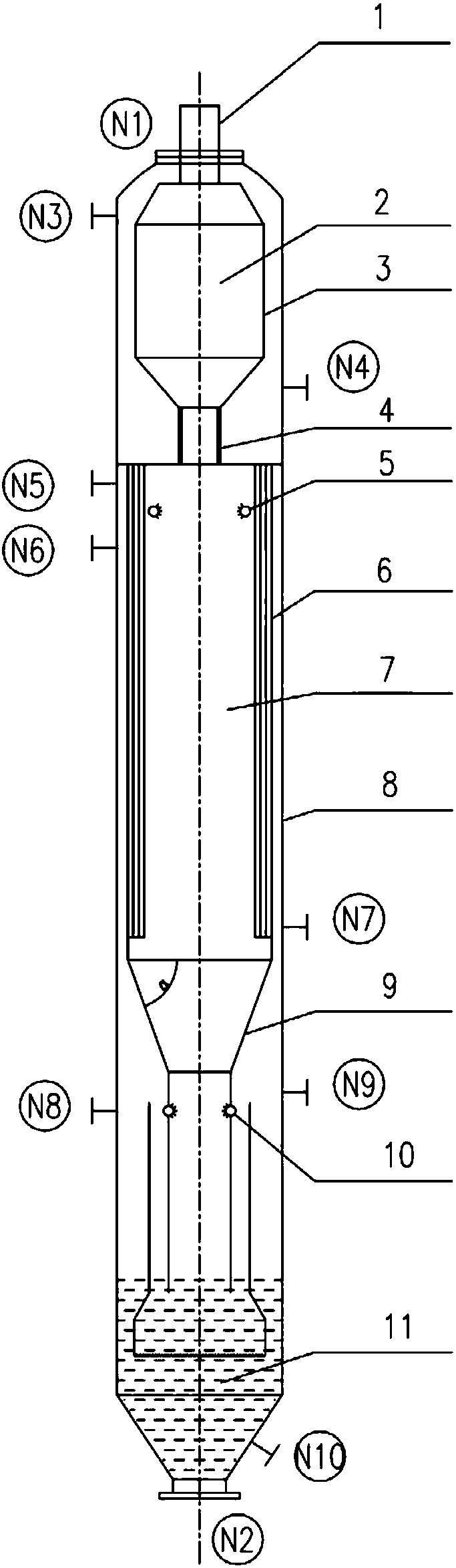
[0051] This embodiment provides a gasifier with radiation heat exchange, the structure of which is as follows figure 1 As shown, it includes a shell 8 and a furnace body arranged in the shell 8. The furnace body includes a gasification chamber, a radiation heat exchange chamber 7 and a quench chamber which are arranged coaxially from top to bottom.

[0052] The gasification chamber includes a burner connection port at the top, a lower slag port 4 with swirling flow at the bottom, and a gasification reaction chamber 2 between the top and the bottom. The burner connection port and the gasification burner 1 connection, the gasification reaction chamber 2 is provided with a water-cooled wall 3; the casing 8 is provided with a gasification chamber water-cooled wall boiler water inlet N4 corresponding to the lower part of the gasification chamber, and the casing 8 corresponds to The upper part of the gasification chamber is provided with a steam and water outlet N3 of the water wall of the

Embodiment 2

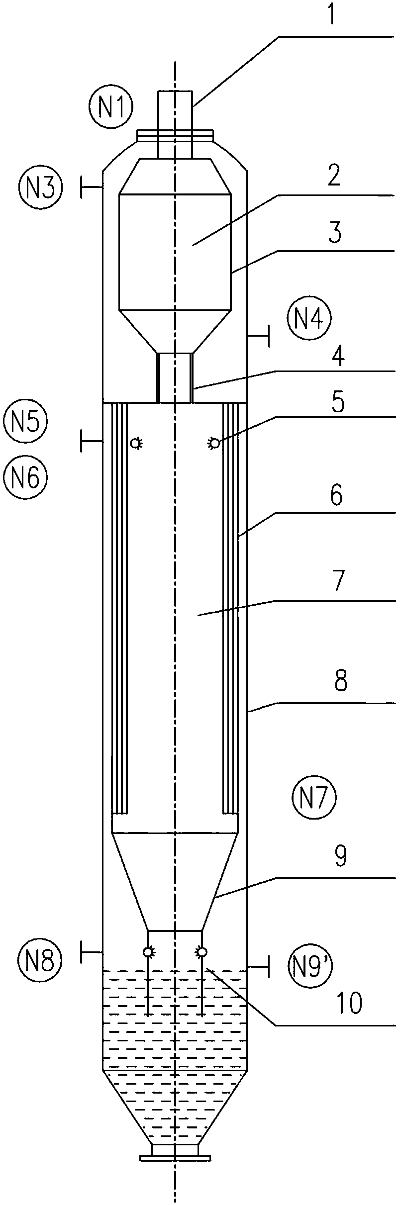
[0063] This embodiment provides another gasifier with radiation heat exchange, the structure of which is as follows image 3 As shown, it includes a shell 8 and a furnace body arranged in the shell 8. The furnace body includes a gasification chamber, a radiation heat exchange chamber 7 and a quench chamber which are arranged coaxially from top to bottom.

[0064] The gasification chamber includes a burner connection port at the top, a lower slag port 4 with swirling flow at the bottom, and a gasification reaction chamber 2 between the top and the bottom. The burner connection port and the gasification burner 1 connection, the gasification reaction chamber 2 is provided with a water-cooled wall 3; the casing 8 is provided with a gasification chamber water-cooled wall boiler water inlet N4 corresponding to the lower part of the gasification chamber, and the casing 8 corresponds to The upper part of the gasification chamber is provided with a steam and water outlet N3 on the water wall


PUM


Abstract

The invention relates to a gasification furnace with radiation heat exchange and a gasification method. The gasification furnace includes a shell and a furnace body. The furnace body includes a gasification chamber, a radiation heat exchange chamber and a shock chamber which are arranged coaxially in sequence from top to bottom. A burner connection port is formed in the top of the gasification chamber, raw coal and pure oxygen are sprayed into the gasification chamber through a burner to perform a coal gasification reaction, crude synthesis gas and molten ash after the reaction swirl down to enter a slag discharging port. Constrained by the special swirling structure of the slag discharging port, the gas flow and molten ash entering the radiation heat exchange chamber still maintain a swirling manifold, the following performance of the ash and gas flow in the crude synthesis gas is maintained, the collision between the ash and between the ash and the inner wall of a radiation heat exchanger is reduced, and the probability of random diffusion of the ash to the inner wall surface of the radiation heat exchange chamber is greatly reduced. Meanwhile, a heat exchange screen on the innerwall surface of the radiation heat exchanger is deflected by a certain angle in the direction of swirling flow, not only the slag passing diameter is increased, but also the disturbance of the inneredge of the heat exchange screen on the gas flow is reduced, so that the risks of slag bonding and ash deposition are structurally reduced.

Description


Claims


Application Information

Patent Timeline
Owner BEIJING AEROSPACE MWAY TECH CO LTD
Why Eureka
Try Eureka