Actuator and wire fixing structure thereof

A technology for fixing structures and actuators, applied in the directions of electric components, casings/covers/supports, electrical components, etc., can solve the problems of loose or falling off of the covering sleeve, unfavorable assembly, wire damage, etc., to improve the use effect. , Simple structure, ensure the effect of normal use

Inactive Publication Date: 2020-01-17
TOYO AUTOMATION CO LTD
View PDF8 Cites 0 Cited by
  • Summary
  • Abstract
  • Description
  • Claims
  • Application Information

AI Technical Summary

Problems solved by technology

However, the conventional fixing method of the wire sheath is not only unfavorable for assembly, it is also easy

Method used


Image

  • Actuator and wire fixing structure thereof
  • Actuator and wire fixing structure thereof
  • Actuator and wire fixing structure thereof

Examples


Example Embodiment

[0030] The present invention may have many different structural embodiments. Now it is only an example but not a specific embodiment for limitation, and with reference to the accompanying drawings, the preferred structural content of the present invention is described as follows:

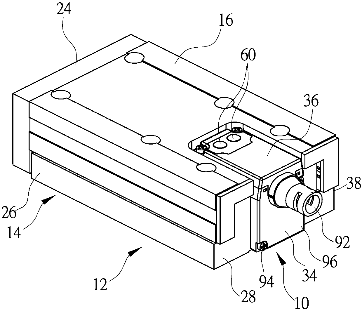
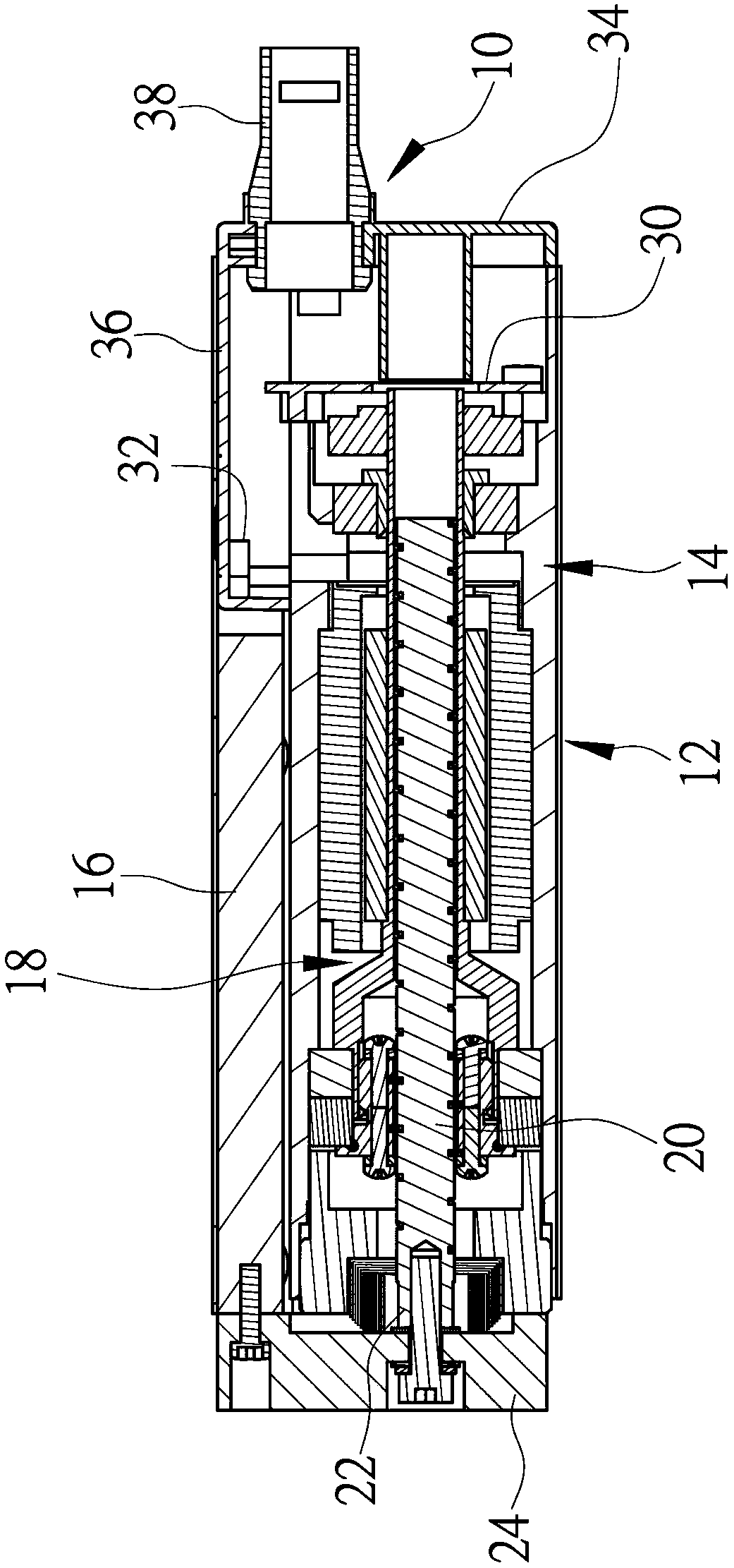
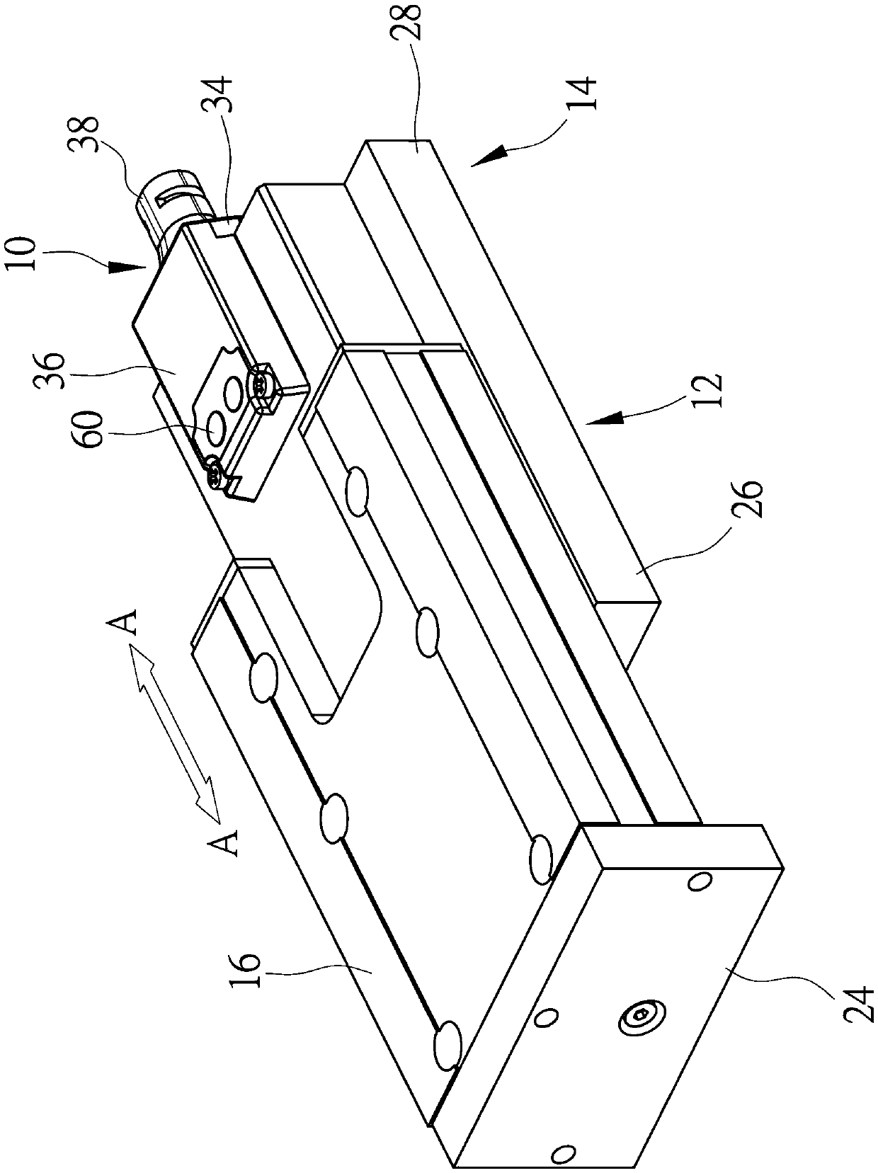
[0031] Figure 1 to Figure 3 An embodiment in which the wire fixing structure 10 according to the present invention is applied to an actuator 12 is shown. In this embodiment, the actuator 12 is an electric cylinder and includes a main body 14 and a sliding seat 16 disposed on the main body 14 . A motor 18 and a screw 20 are arranged inside the main body 14 . The outer end 22 is combined with an output shaft fixing plate 24 , and the fixing plate 24 is combined with the sliding seat 16 . When the motor 18 is running, the screw 20 is driven to drive the fixing plate 24 and the sliding seat 16 along a longitudinal direction of the main body 14 (eg image 3 The direction indicated by the middle arrow A-


PUM


Abstract

The invention relates to an actuator and a wire fixing structure thereof. The wire fixing structure is used for being installed on a body of the actuator, and comprises an end cover, an upper cover and a wire coating seat. The end cover is installed at one end of the body and is provided with a first concave portion and a first abutting portion, and the first concave portion is provided with two first grooves. The upper cover comprises an upper wall and a side wall extending downwards from the rear end of the upper wall, the side wall is combined with the top of the end cover, and the side wall is provided with a second concave portion and a second abutting portion. The second concave portion is provided with two second grooves, the wire coating seat comprises a necking part, and the necking part is assembled in the first concave part and the second concave part and is provided with two protruding points. The two protruding points are located in the first groove and the second groove,the front edge of the necking part is provided with a bearing face, and the bearing face abuts against the first abutting part and the second abutting part.

Description


Claims


Application Information

Patent Timeline
Owner TOYO AUTOMATION CO LTD
Why Eureka
Try Eureka