Temperature sensor fault diagnosis method and temperature sensor fault diagnosis system

A temperature sensor and fault diagnosis technology, applied in thermometers, thermometer testing/calibration, instruments, etc., can solve problems such as inability to diagnose temperature sensor zero offset faults, and achieve the effect of reducing costs

Inactive Publication Date: 2020-01-21
WEICHAI POWER CO LTD
View PDF5 Cites 8 Cited by
  • Summary
  • Abstract
  • Description
  • Claims
  • Application Information

AI Technical Summary

Benefits of technology

In this patented system, if there are any errors or deviations from expected values during operation due to factors like fuel quality issues that could affect the performance of an internal combustion engine (engine) under certain conditions such as low temperatures). When these problems occur it may lead to damage caused by excessive heating or other causes. To prevent further damaging accidents, some systems use thermistors placed near each cylinder's exhaust pipe to detect leaks on their own. However, current methods require multiple sensors at different locations along with complex algorithms involving complicated calculations which makes them expensive compared to traditional approaches.

Problems solved by technology

Technically speaking, this patented technical problem addressed in the previous paragraphs involves determining if an electronic device's temperature sensor works correctly when compared with other devices without any issues such as overheating or incorrect operation caused due to improper installation.

Method used


Image

  • Temperature sensor fault diagnosis method and temperature sensor fault diagnosis system
  • Temperature sensor fault diagnosis method and temperature sensor fault diagnosis system
  • Temperature sensor fault diagnosis method and temperature sensor fault diagnosis system

Examples


Embodiment Construction

[0051] Exemplary embodiments of the present disclosure will be described in more detail below with reference to the accompanying drawings. While exemplary embodiments of the present disclosure are shown in the drawings, it should be understood that the present disclosure may be embodied in various forms and should not be limited by the embodiments set forth herein. Rather, these embodiments are provided so that the present disclosure will be more thoroughly understood, and will fully convey the scope of the present disclosure to those skilled in the art.

[0052] It is to be understood that the terminology used herein is for the purpose of describing particular example embodiments only and is not intended to be limiting. As used herein, the singular forms "a," "an," and "the" can also be intended to include the plural forms unless the context clearly dictates otherwise. The terms "comprising", "comprising", "containing" and "having" are inclusive and thus indicate the presence o


PUM


Abstract

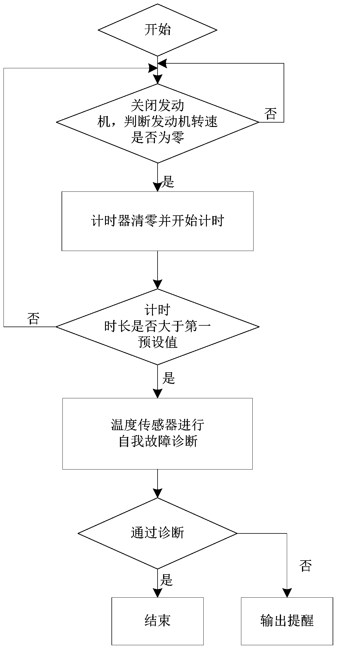
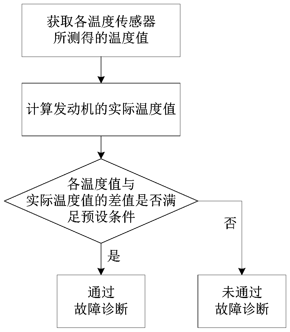
The invention belongs to the technical field of an engine, and particularly relates to a temperature sensor fault diagnosis method and a temperature sensor fault diagnosis system. The temperature sensor fault diagnosis method comprises the following steps of turning off an engine; judging whether the rotating speed of the engine is zero or not; if the rotating speed of the engine is zero, resetting a timer and starting timing; when the timing duration is smaller than a first preset value, and the engine is started, performing timing again after the engine is turned off; when the timing duration is greater than the first preset value, performing self fault diagnosis by temperature sensors; if the fault diagnosis is not passed, outputting reminding; and if the fault diagnosis is passed, ending the diagnosis. The temperature sensor fault diagnosis method according to the embodiment has the advantages that when the engine turning-off time reaches the first preset time, the temperature values measured by the temperature sensors arranged in each position of the engine are in an allowable error range; and the measuring values of each temperature sensor are compared for judging whether thetemperature sensors generate a zero offset fault or not.

Description


Claims


Application Information

Patent Timeline
Owner WEICHAI POWER CO LTD
Why Eureka
Try Eureka