Sleep state identification method and device

A sleep state and identification method technology, applied in medical science, sensors, diagnostic recording/measurement, etc., can solve problems such as inflexibility, inability to adapt to different user sleep habits, and inability to personalize user settings

Inactive Publication Date: 2020-02-04
HUAWEI TECH CO LTD
View PDF9 Cites 5 Cited by
  • Summary
  • Abstract
  • Description
  • Claims
  • Application Information

AI Technical Summary

Benefits of technology

The present technology allows for more efficient use of space during construction or maintenance tasks compared with previous designs that were meant only once before it was done. This means less time needed on site when working around things like wires bundles or pipes.

Problems solved by technology

This patented technical problem addressed by this patents relates to improving how an electronics device responds based on its own states during periods where they are either awake or dormant. Current methods rely solely upon predetermined settings that may be too rigid because people's sleep patterns change over time due to factors like their activity level.

Method used


Image

  • Sleep state identification method and device
  • Sleep state identification method and device
  • Sleep state identification method and device

Examples


Embodiment Construction

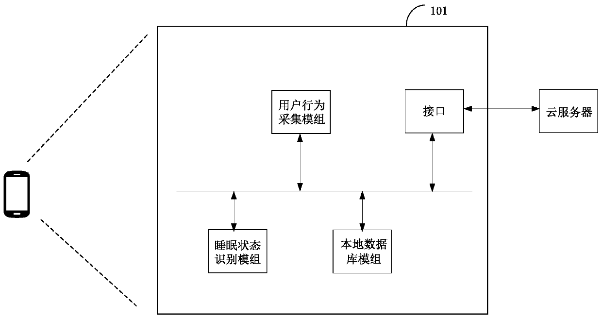
[0031] In order to flexibly determine whether the user is in a sleep state, an embodiment of the present application provides a method for identifying a sleep state. In this method, the electronic device 101 can determine the user's personalized sleep time period through the neural network model, and judge whether the user is in a sleep state during the sleep time period. Compared with the prior art, it can obtain a judgment result that is more in line with the user's sleep habits.

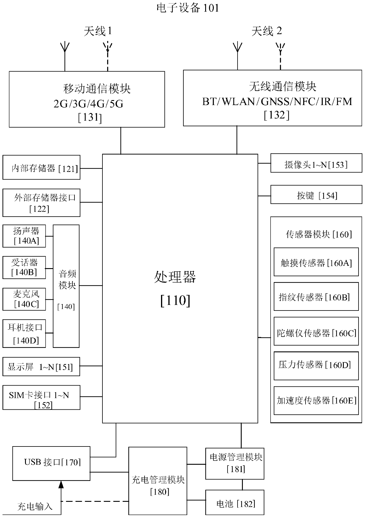
[0032] The sleep state identification method provided by the embodiment of the present application can be applied to any electronic device, and the electronic device can also be called user equipment (user equipment, UE), mobile station (mobile station, MS), mobile terminal (mobile terminal, MT) Wait. For example, handheld devices with wireless connectivity, vehicle-mounted devices, or vehicle-mounted devices, etc. Electronic equipment may also include, but is not limited to Android, Microsoft O


PUM


Abstract

The invention provides a sleep state identification method and device. By adopting the state identification method and device, a personalized sleep time period of a user can be determined by electronic equipment according to a personalized sleep state identification model of the user, and in the personalized sleep time period of the user, whether the user is truly in a sleep state or not is judgedaccording to collected data used for identifying whether the user is in the sleep state or not, so that an identification result of the sleep state more accords with a sleep habit of the user.

Description


Claims


Application Information

Patent Timeline
Owner HUAWEI TECH CO LTD
Why Eureka
Try Eureka