Sludge concentration plant for water environment treatment

A technology for sludge concentration and water environment, applied in water/sludge/sewage treatment, dewatering/drying/concentrated sludge treatment, sludge treatment, etc. The problems of high efficiency and sludge moisture content can reduce manpower input, improve efficiency and high concentration efficiency.

Active Publication Date: 2020-02-14
莘县鲁开综合服务有限公司
View PDF3 Cites 0 Cited by
  • Summary
  • Abstract
  • Description
  • Claims
  • Application Information

AI Technical Summary

Benefits of technology

This patented technology describes an apparatus called a slurry concentrate (Sys) container or drum system. These systems help separate liquid waste into two parts - one containing high-concentrations of solids like plasma residue while another part contains low levels of dissolved materials such as nitrogen compounds. By moving these liquids together during processing, they become easier to dispose of compared to traditional methods where all them must go back down again once processed. Additionally, there may also include a mechanism to automate the removal of heavy metals from sludges before disposal, allowing for quicker and less laborious treatments. Overall, these technical features enhance the performance and cost savings associated with existing technologies.

Problems solved by technology

This patents describes different ways to improve the effectiveness or ease with removing solid particles (sludges) found on surfaces like lakes). One way involves adding chemical agents into wastewater, such as chlorine gas, to make it easier to separate smaller ones by gravity instead of relying solely upon gravitational forces. Another approach suggests utilizing special equipment called an inclined plate separator system, which helps keep larger solids suspended while still allowing liquid to flow through without being separated. However, these methods require significant effort and may result in residue left behind overtime due to their slow sedimentation rate. Additionally, current systems have limitations when handling large amounts of slurry containing heavy metals.

Method used


Image

  • Sludge concentration plant for water environment treatment
  • Sludge concentration plant for water environment treatment
  • Sludge concentration plant for water environment treatment

Examples


Embodiment

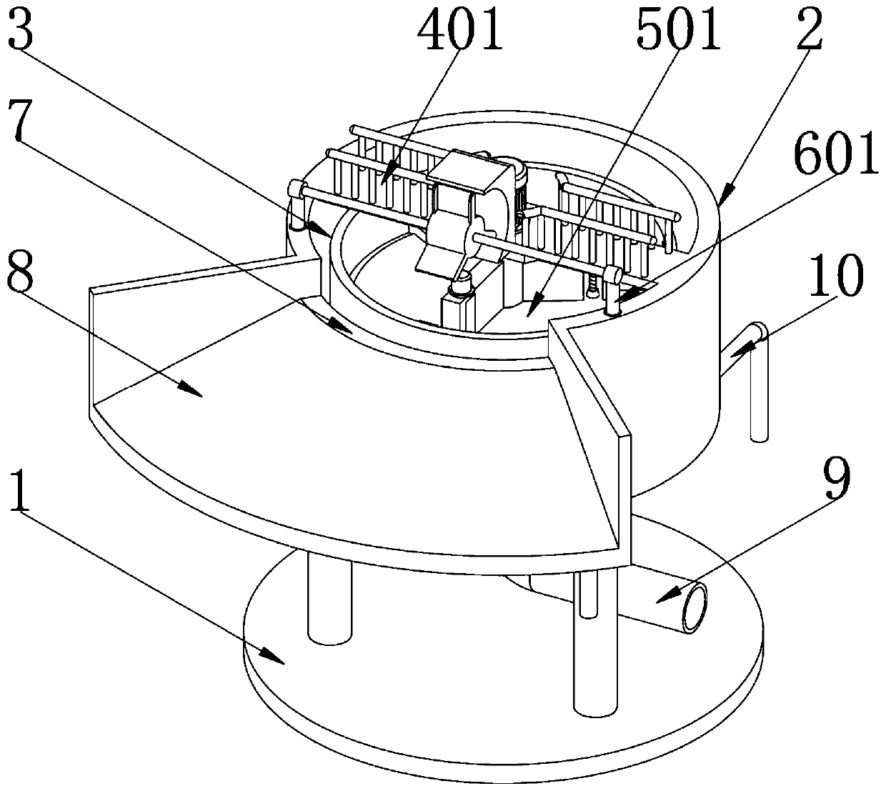
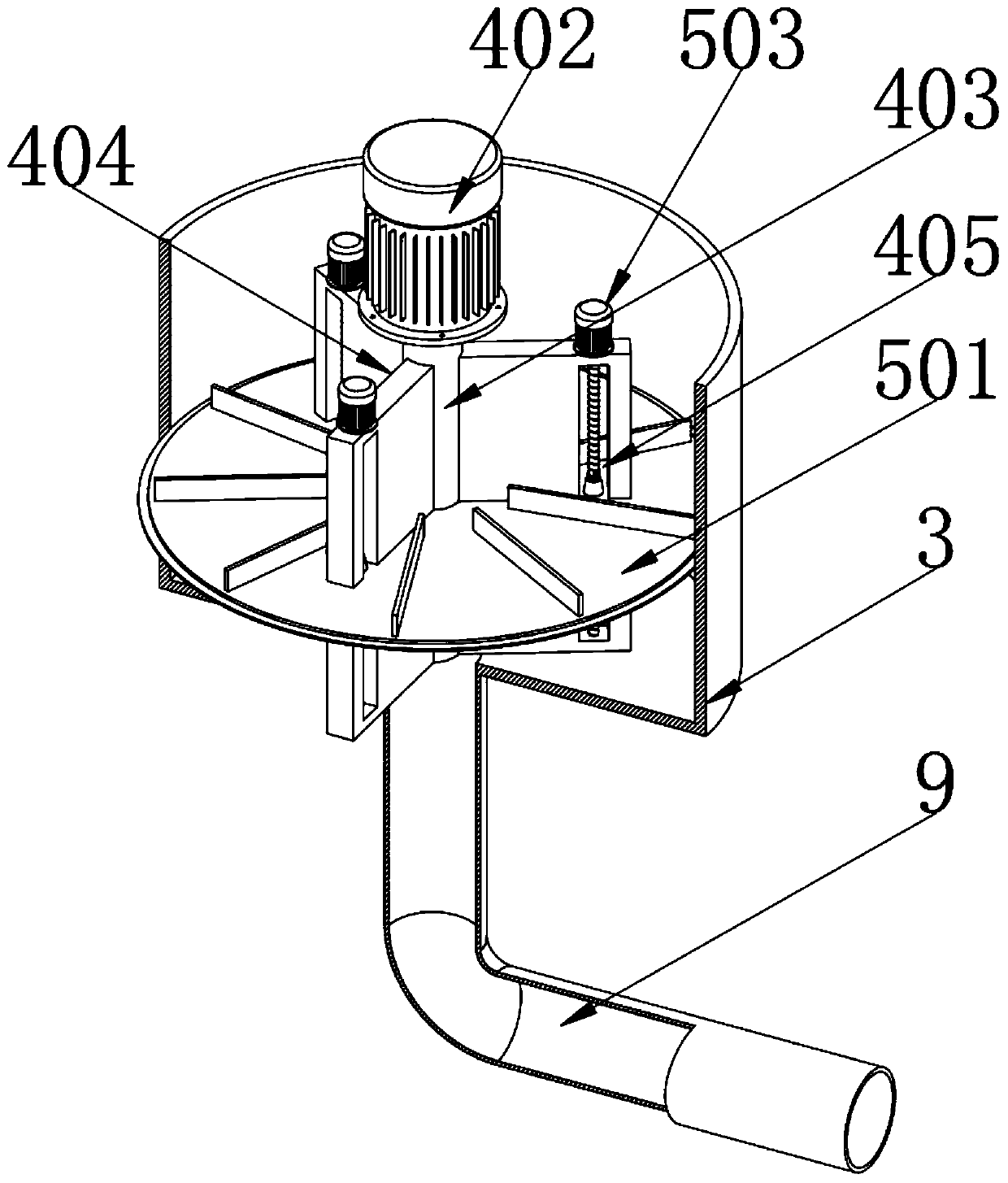
[0046] Example: such as Figure 1-6 As shown, a sludge concentration device for water environment treatment includes a support base 1, an outer tank body 2 and an inner tank body 3, an outer tank body 2 is fixedly installed above the support base 1, and an inner tank body 2 is fixedly installed inside the outer tank body 2. The tank body 3, the inner tank body 1 is equipped with a centrifugal component 4 for providing centrifugal force, which is used to provide centrifugal force for the muddy water inside the inner tank body 3, so that the sludge is separated from the water due to its high density and settles, completing the process of For the concentration of sludge, a lifting component 5 for lifting the sludge is installed on the outside of the centrifugal component 4, which is used to lift the concentrated sludge to the top of the inner tank 3, so as to facilitate the discharge of the concentrated sludge and avoid manual entry The inside of the inner tank body 3 processes the


PUM


Abstract

The invention belongs to the technical field of water environment treatment, and in particular discloses a sludge concentration plant for water environment treatment. The sludge concentration plant comprises a supporting base. An outer tank is fixedly mounted above the supporting base. An inner tank is fixedly mounted in the outer tank. A centrifugal assembly is mounted in the inner tank. A lifting assembly is mounted on the outer side of the centrifugal assembly. The sludge concentration plant for water environment treatment is scientific and reasonable, and safe and convenient in use; a lifting motor rotates to drive a threaded rod to rotate, causing a threaded seat to move upwards while the threaded rod rotates; then, a lifting plate moves upwards under the action of the threaded seat,causing sludge precipitated on the lifting plate to move upwards inside the inner tank; thus, workers do not need to enter the inner tank to dispose sludge precipitated at the bottom end of the innertank, and manpower is saved; moreover, sludge concentrated on the threaded rod can be removed by using a sludge removing spiral plate, avoiding the sludge concentrated on the threaded rod from influencing normal lifting of the lifting plate and allowing for more smooth lifting of the lifting plate.

Description


Claims


Application Information

Patent Timeline
Owner 莘县鲁开综合服务有限公司
Why Eureka
Try Eureka