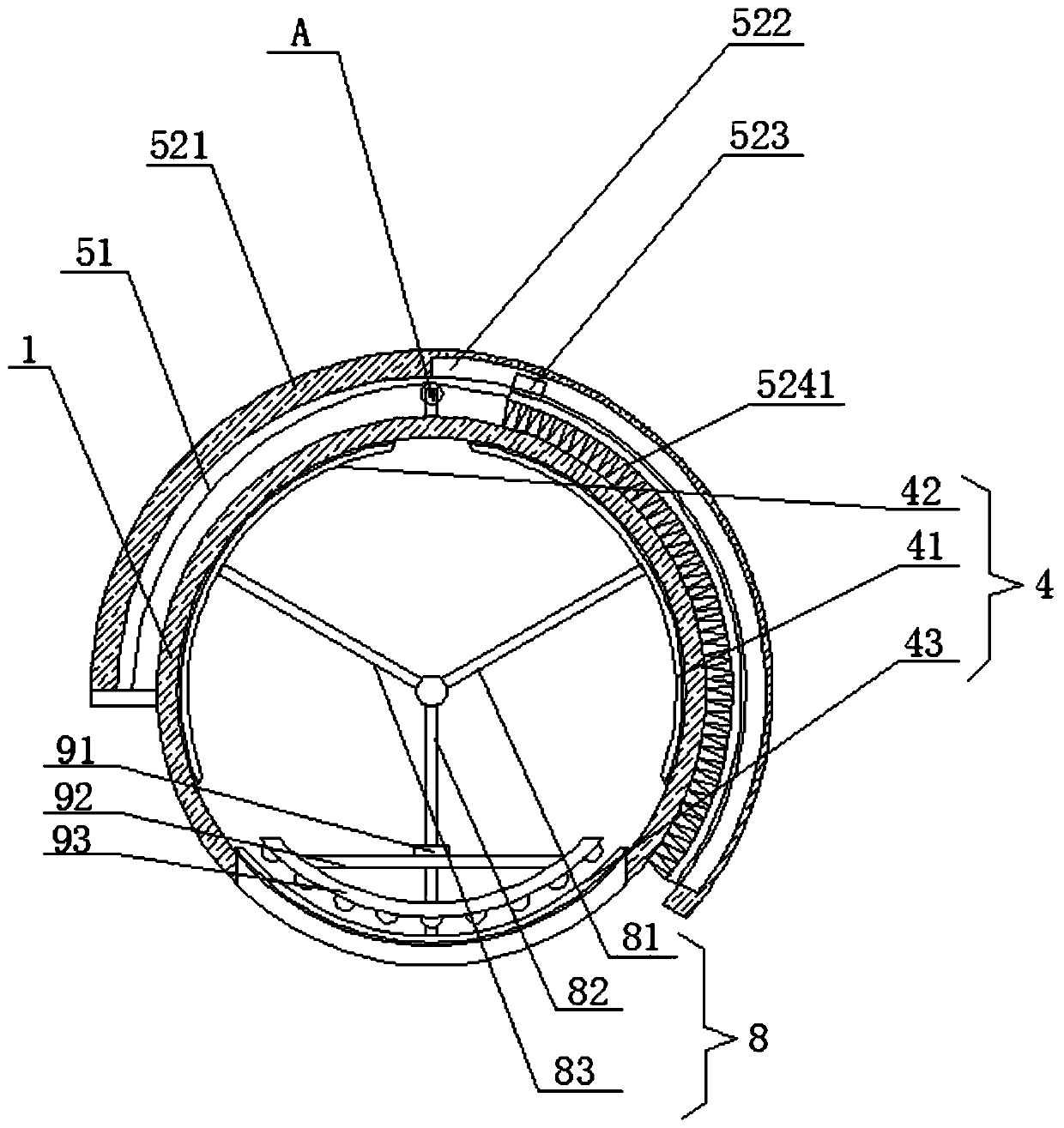
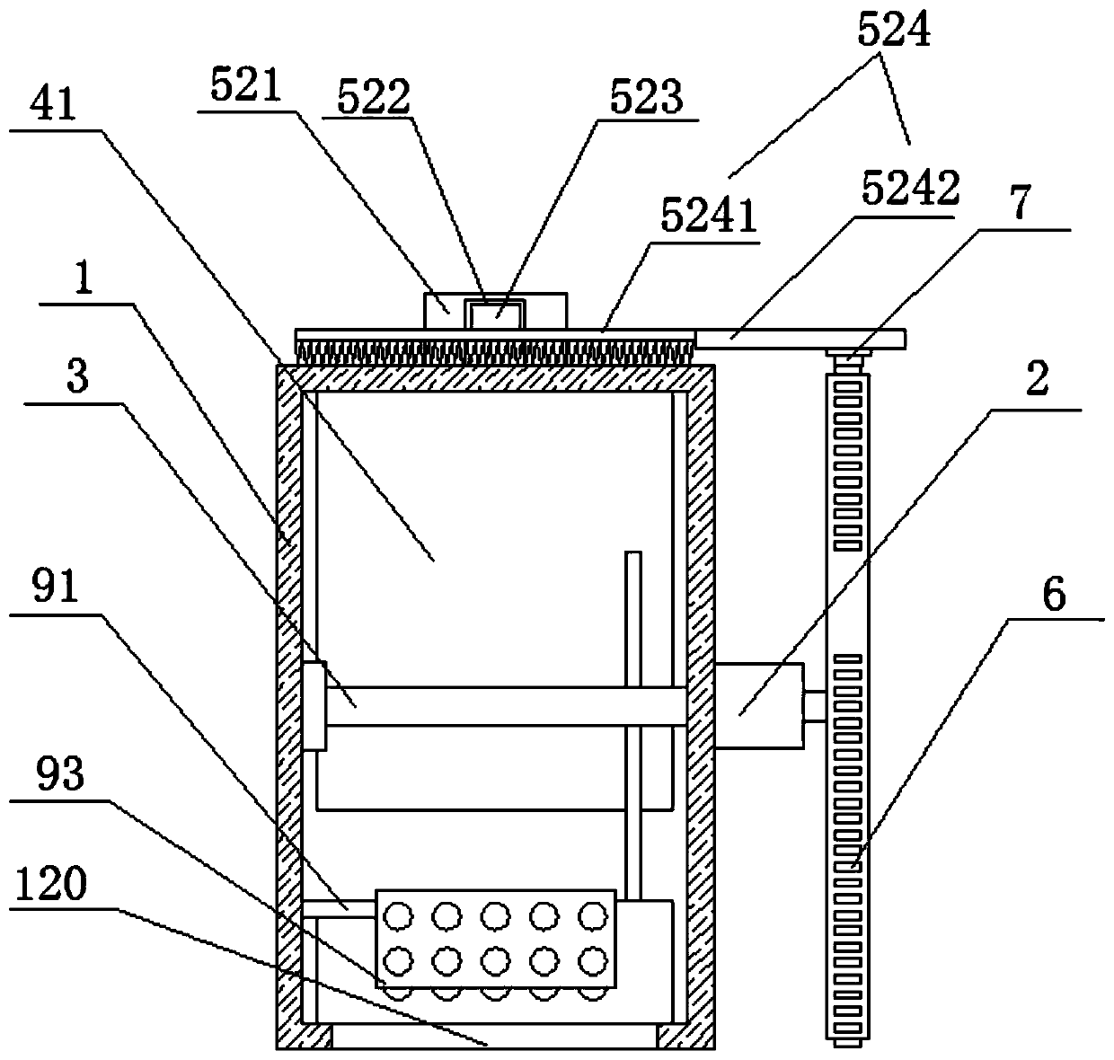
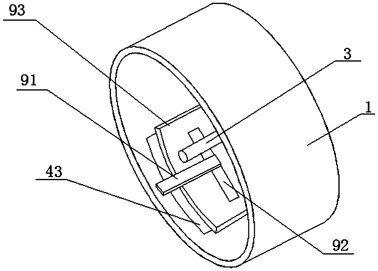
LED package structure

A technology of LED packaging and LED lamp components, which is applied in the direction of lighting devices, lighting device parts, cleaning and flexible objects, etc., can solve the problems of manual cleaning of LED lights, inconvenient, unfavorable promotion, etc., to facilitate the exchange of color temperature and improve lighting effect, the effect of novel design

Active Publication Date: 2020-03-06
宁波安芯美半导体有限公司
View PDF7 Cites 0 Cited by
  • Summary
  • Abstract
  • Description
  • Claims
  • Application Information

AI Technical Summary

Benefits of technology

This patented technology allows for easy adjustment of colors emitted from one lamp without having to replace or repair any other parts on top. It uses an engine-driven system where there are two main components - a motorized wheel and a set of cables attached between them. When turning this wheels, they cause rotation through certain mechanisms called motors, causing the entire assembly to revolve around itself. These movements help create patterns of varying degrees of brightness across various colored lights. By controllably moving these systems back and forth over time, users have more flexibility than traditional lamps due to their ability to switch among multiple types of wavelengths based upon factors like ambient conditions such as sunlight level.

Problems solved by technology

This patented technical problem addressed by this patents relates to improving the efficiency or flexibility of LED lights that are currently available for both traditional types (monochrome) and colored versions thereof due to their limited range of colors emitted from them. Additionally, current solutions require multiple bulbs with specific wavelength ranges, making maintenance difficult without causing damage on other components such as circuitry.

Method used


Image

  • LED package structure
  • LED package structure
  • LED package structure

Examples


Embodiment Construction

[0061] The implementation of the present invention is described below through specific specific examples, and those skilled in the art can easily understand other advantages and effects of the present invention from the content disclosed in this specification. The present invention can also be implemented or applied through other different specific implementation modes, and various modifications or changes can be made to the details in this specification based on different viewpoints and applications without departing from the spirit of the present invention. It should be noted that, in the case of no conflict, the following embodiments and features in the embodiments can be combined with each other. It should also be understood that the terminology used in the embodiments of the present invention is for describing specific implementations, not for limiting the protection scope of the present invention. The test methods for which specific conditions are not indicated in the follo


PUM


Abstract

The invention discloses an LED package structure. The structure comprises a box body, a driving mechanism, a cleaning device, a rotating shaft, a color palette, and an LED lamp component. An outer wall of the box body and a glass cover of the box body can be cleaned while changing the color palette every time.

Description


Claims


Application Information

Patent Timeline
Owner 宁波安芯美半导体有限公司
Why Eureka
Try Eureka