Device for storing compressed fluids

A technology for compressing fluids and technical devices, which is applied in the field of devices storing compressed fluids, can solve the problems of not considering the use of large-scale vehicle bodies, and not meeting size requirements, and achieve the effects of small heating, non-flammable costs, and high thermal conductivity.

Pending Publication Date: 2020-04-03
ROBERT BOSCH GMBH
View PDF7 Cites 1 Cited by
  • Summary
  • Abstract
  • Description
  • Claims
  • Application Information

AI Technical Summary

Benefits of technology

This patented technical solution described in the present describes various embodiments related to devices called pressure containers (PVs). These PvSIs have several benefits compared to existing systems: they allow for flexible mountings without requiring bulky components like steel; their dimensions may vary depending on how much liquid needs them inside; they offer better cooling performance than traditional methods based solely upon conduction properties alone; they require less expensive materials because there're no harmful substances involved in previous designs. Overall these improvements improve efficiency and usability of stored compressors.

Problems solved by technology

This patents describes how current types of hydraulic gas cylindrical vessels (HGV) experience heat stress due to their structure being complicated and expensive to produce. There exists a technical solution where HVG' s tank volume needs to be reduced without compromising safety concerns.

Method used


Image

  • Device for storing compressed fluids
  • Device for storing compressed fluids
  • Device for storing compressed fluids

Examples


Embodiment Construction

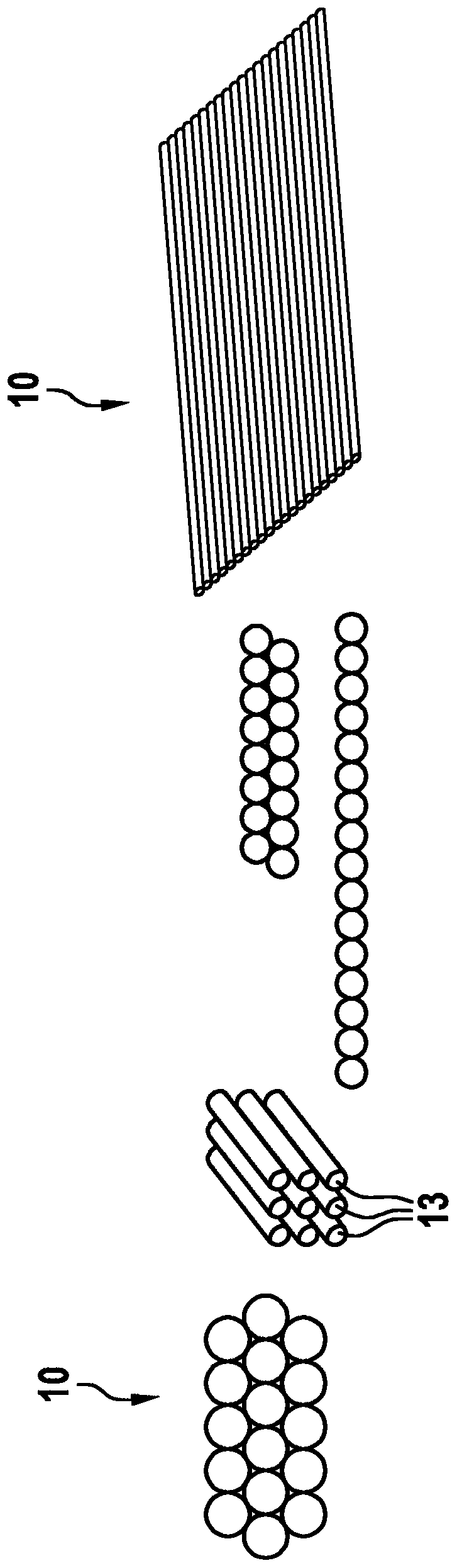
[0030] exist figure 1 A schematic diagram of the modular construction of the device 10 for storing compressed fluid consisting of tank modules is shown in . The device 10 consists of a series of tank modules 13 made of metal. The individual tank modules 13 can be produced from tubular semi-finished products. The tank modules 13 can be arranged as a stack on top of each other or next to each other and can be produced in any desired length. The tank module 13 is connected via at least one high-pressure fuel distributor 14 to at least one integrated control and safety technology device 15 .

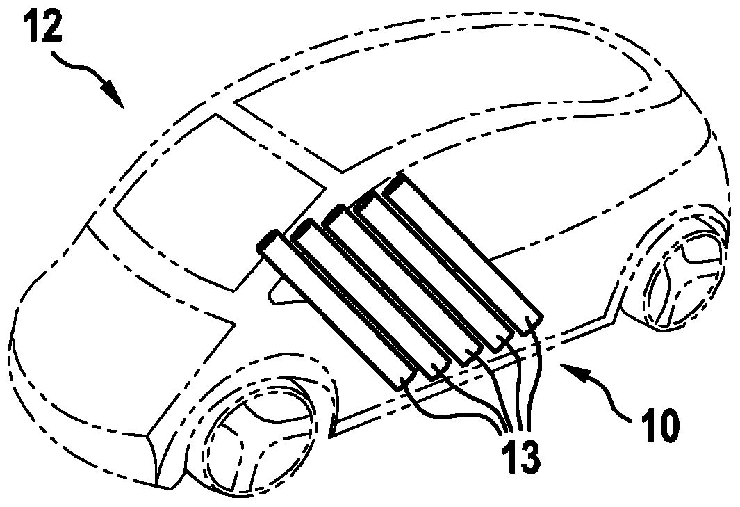
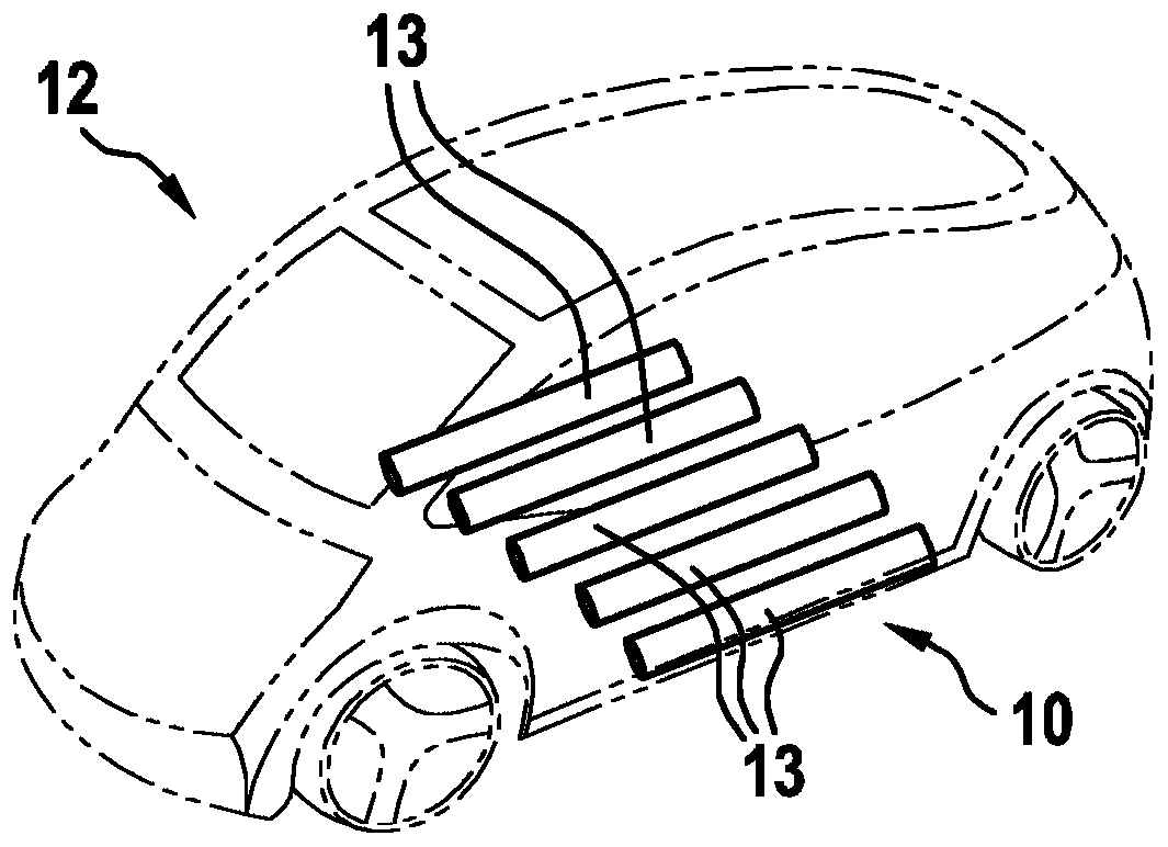
[0031] figure 2 A schematic view of a vehicle 12 is shown with a device 10 for storing compressed fluid, which is made up of tank modules 13 and is installed transversely in the vehicle floor. In this vehicle 12 , the tank module 13 is arranged transversely to the direction of travel of the vehicle 12 . The arrangement of the tank module 13 below the passenger compartment of the vehicle 1


PUM


Abstract

The invention relates to a device for storing compressed fluids for a vehicle driven by means of gaseous fuels, the device comprising at least two tubular tank modules and at least one high-pressure fuel distributor having at least one integrated control and safety device, the at least two tubular tank modules consisting of metal and being connected to the at least one high-pressure fuel distributor having the at least one integrated control and safety device modularly to form a module in flexible geometry.

Description


Claims


Application Information

Patent Timeline
Owner ROBERT BOSCH GMBH
Why Eureka
Try Eureka