Ultra-wideband four-ridge horn antenna capable of adjusting diameter of back cavity

A four-ridged horn, adjustable technology, applied in the field of communication, can solve the problem of large difference in performance of antenna feeding ports, and achieve the effect of good impedance matching and port consistency

Inactive Publication Date: 2020-04-10
NANJING CHANGFENG AEROSPACE ELECTRONICS SCI & TECH
View PDF7 Cites 1 Cited by
  • Summary
  • Abstract
  • Description
  • Claims
  • Application Information

AI Technical Summary

Problems solved by technology

[0004] The purpose of the present invention is to provide an ultra-wideband four-ridge horn antenna with an adjustable back cavity diameter, which solves the problem that the

Method used


Image

  • Ultra-wideband four-ridge horn antenna capable of adjusting diameter of back cavity
  • Ultra-wideband four-ridge horn antenna capable of adjusting diameter of back cavity
  • Ultra-wideband four-ridge horn antenna capable of adjusting diameter of back cavity

Examples


Embodiment Construction

[0020] In order to make the technical means, creative features, goals and effects achieved by the present invention easy to understand, the present invention will be further described below in conjunction with the accompanying drawings and specific implementation methods.

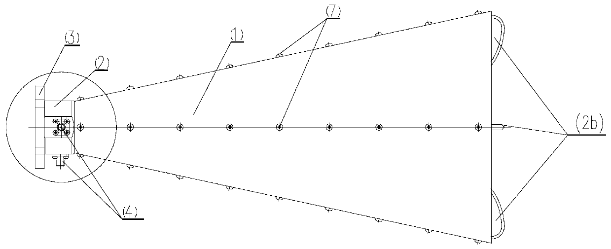
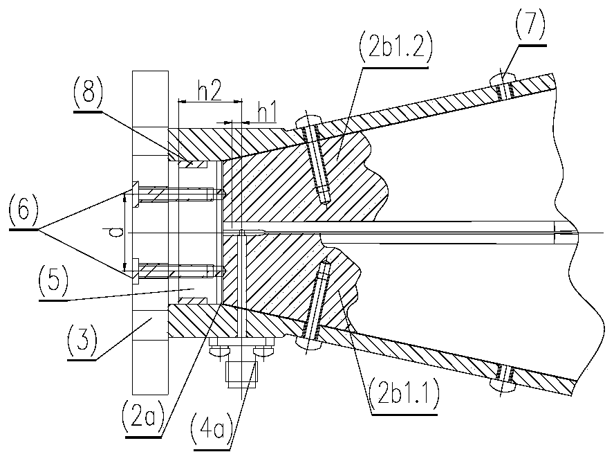
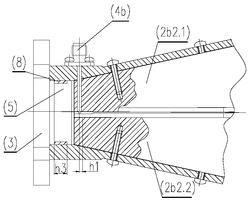
[0021] Such as Figure 1 ~ Figure 4 As shown, an ultra-wideband four-ridge horn antenna with an adjustable back cavity diameter includes a horn 1 (which can be a conical horn), a ridge waveguide 2, a reflective backplane 3, a radio frequency connector 4, and an adjustment screw 6; the ridge The waveguide 2 is connected to the reflective backplane 3, and the adjustment screw 6 penetrates the reflective backplane 3 and then extends into the back cavity 5 formed by the reflective backplane and the ridge waveguide, and short-circuits with the bottom ends of a pair of ridges in the excitation ridge waveguide 2;

[0022] The ridge waveguide 2 includes a waveguide 2a (which may be a circular waveguide) and four ridge


PUM


Abstract

The invention discloses an ultra-wideband four-ridge horn antenna capable of adjusting the diameter of a back cavity. The antennacomprises a horn, a ridge waveguide, a reflecting back plate, a radio frequency connector and a pair of adjusting screws capable of adjusting the distance, wherein one end of the ridge waveguide is connected with the reflecting back plate; and the pair of adjusting screws penetrate into the reflecting back plate and then extend into a back cavity formed by the reflecting back plate and the ridge waveguide to be in short-circuit contact with the pair of ridge sheets of the ridge waveguide. In order to avoid the port difference caused by the up-and-down dislocation of two radio frequency connectors, the pair of adjusting screws are additionally arranged at the bottom of the back cavity, the design difficulty of the ultra-wideband four-ridge horn antenna can be greatly reduced, the method is a novel back cavity design method, and the ridged horn antenna can obtain good port standing waves and good port consistency in an ultra-wideband.

Description


Claims


Application Information

Patent Timeline
Owner NANJING CHANGFENG AEROSPACE ELECTRONICS SCI & TECH
Why Eureka
Try Eureka