CTS slot antenna adopting parabolic cylinder coupled feeding

A parabolic cylinder, coupled feeding technology, applied in the direction of antenna, antenna array, antenna grounding switch structure connection, etc., can solve the problems that the reflector antenna cannot meet the requirements, the design and processing are difficult, and the structure of the feeding network is complex. Achieve the effect of low profile, high radiation efficiency and simplified feeding network

Pending Publication Date: 2018-07-06
北京凌波微步信息技术有限公司
View PDF0 Cites 2 Cited by
  • Summary
  • Abstract
  • Description
  • Claims
  • Application Information

AI Technical Summary

Problems solved by technology

The original high-efficiency reflector antenna cannot meet the requirements
[0005] 3. Requirements for broadband antennas. In the millimeter wave frequency band, various applications are broadband systems, which require the antenna to h

Method used


Image

  • CTS slot antenna adopting parabolic cylinder coupled feeding
  • CTS slot antenna adopting parabolic cylinder coupled feeding
  • CTS slot antenna adopting parabolic cylinder coupled feeding

Examples


Embodiment Construction

[0026] The present invention will be further described in detail below in conjunction with the accompanying drawings and specific embodiments.

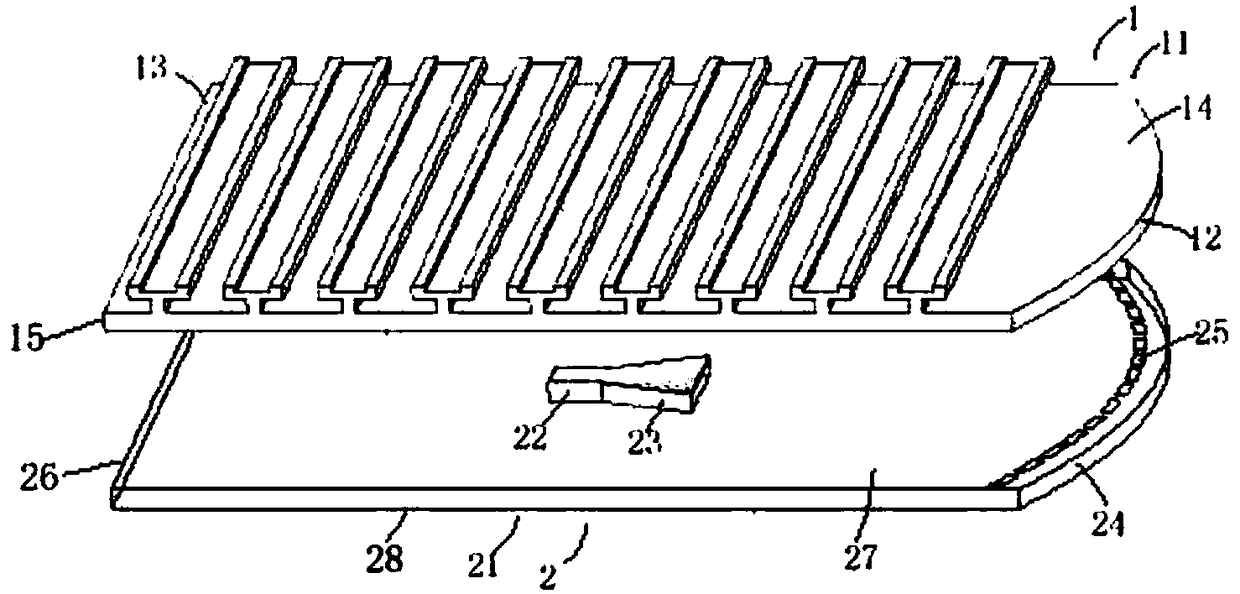
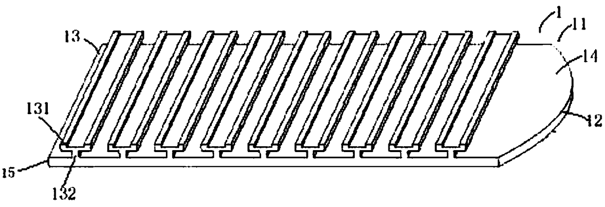
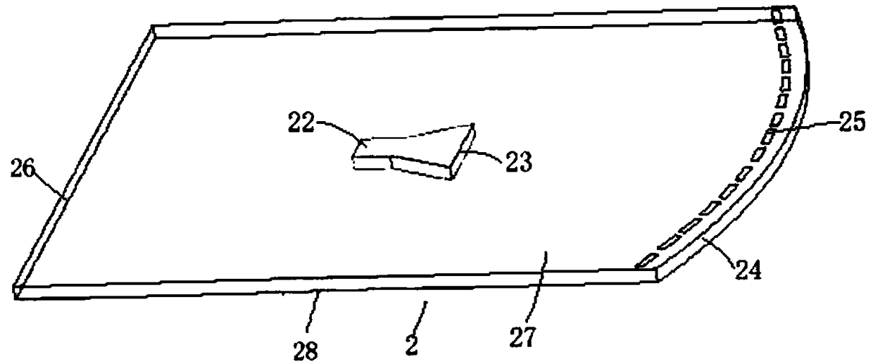
[0027] Such as Figure 1 to Figure 3 As shown, a CTS slot antenna fed by parabolic cylinder coupling includes an upper radiation layer 1 and a lower feed network layer 2. The radiation layer 1 includes a parallel plate waveguide 11, and the upper metal layer located on the side of the parallel plate waveguide 11 A parabolic cylinder 12, a metal plate 15, and a plurality of radiators 13 arranged on the surface of the parallel plate waveguide 11;

[0028] Further, the parallel plate waveguide 11 is surrounded by the first metal plate 14 , the first metal side plate 15 and the upper metal parabolic cylinder 12 .

[0029] A plurality of radiators 13 are located on the surface of the first metal plate 14, and a plurality of radiators 13 are periodically placed at equal intervals in the length direction of the surface of the first metal plate


PUM


Abstract

The invention relates to a CTS slot antenna adopting parabolic cylinder coupled feeding. The slot antenna comprises an upper layer radiation layer and a lower layer feed network layer; the radiation layer comprises a parallel-plate waveguide, an upper layer metal parabolic cylinder positioned on the side surface of the parallel-plate waveguide, and a plurality of radiation bodies arranged on the surface of the parallel-plate waveguide; the feed network layer comprise a feed network layer metal plate main body; the feed network layer metal plate main body is provided with feed waveguide; the feed waveguide is connected with a horn antenna; a lower layer metal parabolic cylinder is arranged on the side surface of the feed network layer metal plate main body; and a series of feed coupled slots are formed in the feed network layer metal plate main body. By virtue of the antenna technology, the feed network is simplified, the feed bandwidth is expanded, the outline is relatively low, and the radiation efficiency is relatively high; and the antenna technology has relatively high advantage in the field of millimeter wave, and can be applied to the fields of millimeter wave radar and communication.

Description


Claims


Application Information

Patent Timeline
Owner 北京凌波微步信息技术有限公司
Why Eureka
Try Eureka