Manufacturing method of special-shaped transparent display screen

A technology of transparent display screen and manufacturing method, which is applied in manufacturing tools, glass manufacturing equipment, instruments, etc., can solve the problem of inability to manufacture special-shaped transparent display screens, and achieve the effect of ideal implementation effect and reasonable manufacturing process design.

Inactive Publication Date: 2020-05-05
TIANJIN CECEP BRILLSHOW
View PDF0 Cites 4 Cited by
  • Summary
  • Abstract
  • Description
  • Claims
  • Application Information

AI Technical Summary

Benefits of technology

This technology allows creation of noncircular shaped displays that are more flexible in terms of their structure compared to regular rectangular ones while still maintaining good quality images on them due to its ability to accurately control the location where light sources appear when they emit colored lights or patterns onto films during production. Additionally, by cutting off unnecessary parts after covering certain areas, these processes become safer and easier to implement. Overall, this new method simplifies the manufacturing procedure and improves productivity efficiency.

Problems solved by technology

The problem addressed in this patented technology relates to creating an opaque screen that meets both high-quality standards (transparent) and easy maintenance without sacrificially compromising its strength or quality level. This requires developing new materials and processes that allow for flexibility while maintaining their effectiveness over time.

Method used


Image

  • Manufacturing method of special-shaped transparent display screen
  • Manufacturing method of special-shaped transparent display screen

Examples


Embodiment Construction

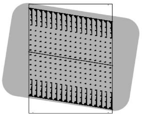
[0034] A method for manufacturing a special-shaped transparent display screen, comprising the following steps:

[0035] The first step is cutting design and etching design of ITO glass and COVER glass;

[0036] When designing cutting, the principle of minimizing the remaining amount is the principle, taking into account the size of the glass, on the premise of providing a uniform voltage to the LED chip, considering the resistivity and optimizing the etching design at the same time, when designing the glass cutting method, try to consider The size of the remaining glass after cutting is easy to use again. Since 1mm of the edge needs to be consumed during cutting, the cutting design should be 1mm larger than the original design size;

[0037] When etching design, design the etching design according to the dimmers and their respective control methods;

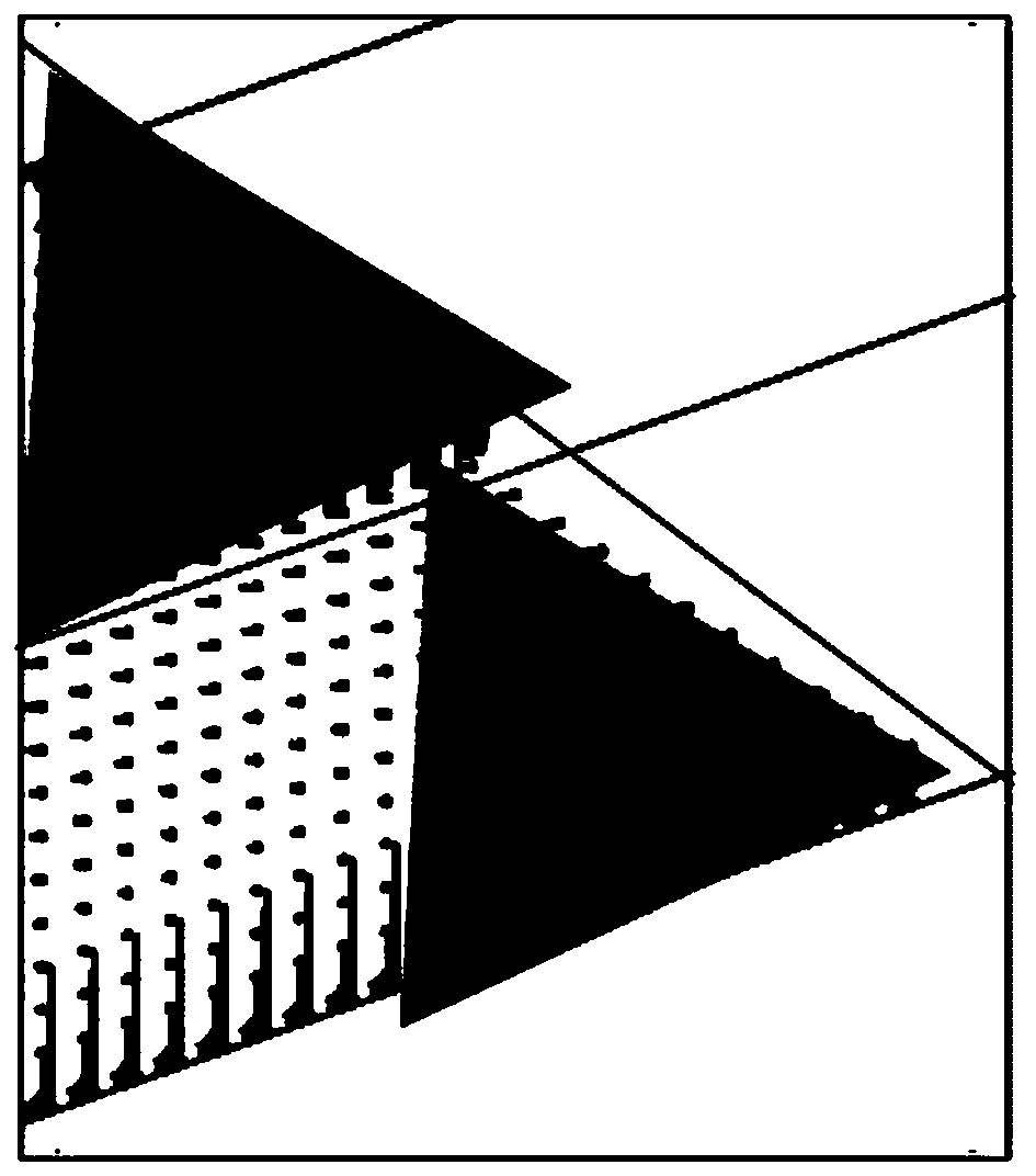
[0038]When designing a parallelogram, in order to ensure the machining accuracy of the etching machine and the placement machine


PUM


Abstract

The invention belongs to the technical field of display screen processing, in particular to a manufacturing method of a special-shaped transparent display screen. During design of parallelogram, the parallelogram must be supplemented to be rectangular for machining; a supplementation direction is selected, poor connection caused by the fact that the same line is divided into different laser headsfor processing is avoided; the direction should be noticed when the parallelogram is completed; during pattern design, designing is carried out by taking an etching pattern as a reference; film cutting is carried out, under limitation by the working principle of a bonding machine (only the glass edge can be machined within the range of 3-5 mm, and the advancing direction is a straight line). The supplemented rectangle must be cut; the FPCB edge can be processed only after being manufactured into the glass edge, and in order to protect the pasted LED CHIP from being damaged, an anti-adhesive tape and a film are adopted to cover the part above the FPCB line, and then cutting, breaking and subsequent processing are carried out until binding is finished, and differentiated production of the parallelogram and a standard product is completely finished.

Description


Claims


Application Information

Patent Timeline
Owner TIANJIN CECEP BRILLSHOW
Why Eureka
Try Eureka