Lift type underground ring main unit based automatic water drainage system

An automatic drainage and lifting technology, applied in infrastructure engineering, construction, etc., can solve the problems of ring network cabinet damage, water inflow, safety accidents, etc., to achieve easy production and installation, strong practicability, and not easy to damage. Effect

Pending Publication Date: 2020-05-29
NANJING GAOLI CONSTR MASCH CO LTD
View PDF0 Cites 2 Cited by
  • Summary
  • Abstract
  • Description
  • Claims
  • Application Information

AI Technical Summary

Benefits of technology

This new technology solves problems by preventing soil from entering through gaps between raised parts or other areas that may allow excessive moisture to get inside during construction without affecting its performance. It also prevents damage caused by rainwater leaks around it's edges while maintaining good insulating properties for longer periods of time.

Problems solved by technology

This patented technology describes how adding a verbal or visual indication can help people see what they are doing inside their cabinets without getting stuck indoors due to lack of space for other things like street lights. Additionally, this design helps reduce environmental concerns by making it easier to clean up after use.

Method used


Image

  • Lift type underground ring main unit based automatic water drainage system
  • Lift type underground ring main unit based automatic water drainage system
  • Lift type underground ring main unit based automatic water drainage system

Examples


Embodiment Construction

[0028] The following will clearly and completely describe the technical solutions in the embodiments of the present invention with reference to the accompanying drawings in the embodiments of the present invention. Obviously, the described embodiments are only some of the embodiments of the present invention, not all of them. Based on the embodiments of the present invention, all other embodiments obtained by persons of ordinary skill in the art without making creative efforts belong to the protection scope of the present invention.

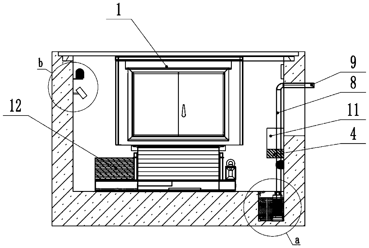
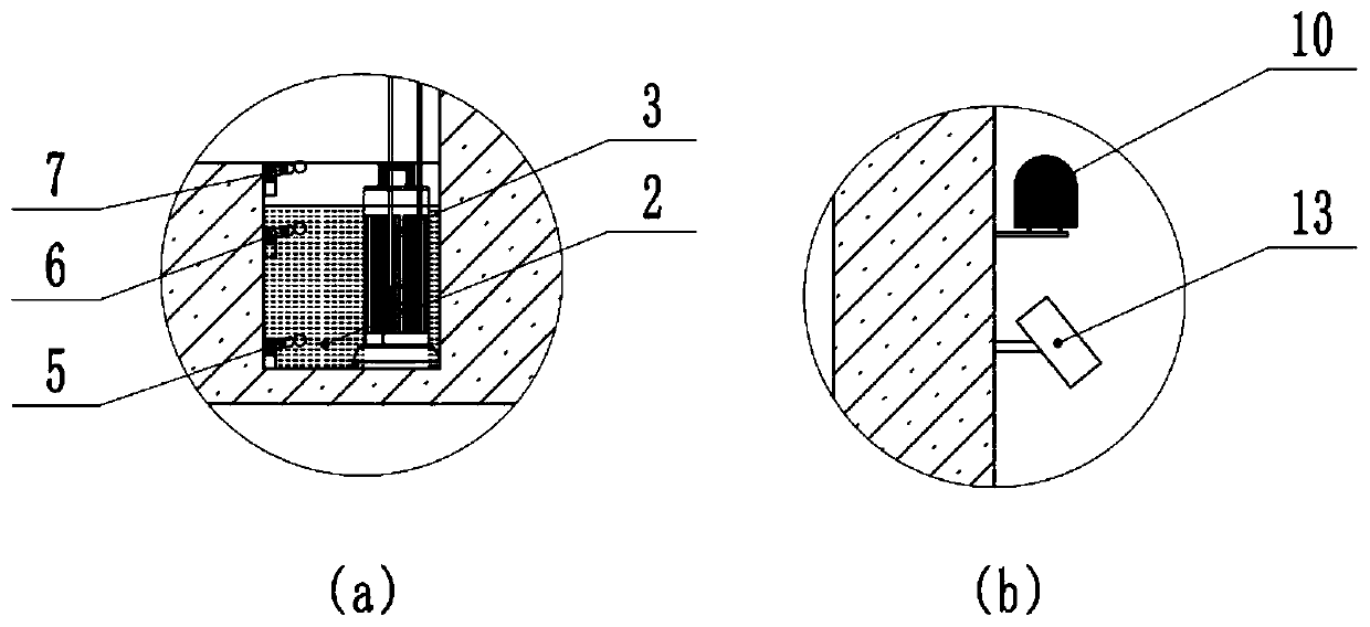
[0029] see Figure 1~2 , an automatic drainage system based on a lift-type buried ring network cabinet in an embodiment of the present invention. Level gauge 5, second liquid level gauge 6, third liquid level gauge 7, drain pipe 8, check valve 9, sound and light alarm 10, automatic dialing device 11, backup power supply 12, camera monitoring device 13, client terminal 14 , foundation pit 15.

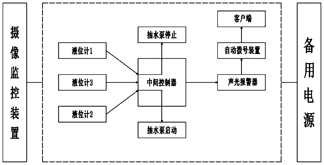
[0030] See image 3 The working principle diagram of


PUM


Abstract

The invention discloses a lift type underground ring main unit based automatic water drainage system. The lift type underground ring main unit based automatic water drainage system comprises a lift type underground ring main unit integral structure, a water accumulating pond, a submersible pump, a middle controller, a first liquid level meter, a second liquid level meter, a third liquid level meter, a water drainage tube, a non-return valve, an audible and visual alarm, an automatic dialing device, a standby power supply, a photographic device, a client side and a foundation pit, wherein whileaccumulated water reaches the position of the second liquid level meter, a signal is transmitted to the middle controller to control the submersible pump to start, and water is extracted and discharged into an urban drainage pipeline through the submersible pump; while accumulated water reduces to the position of the first liquid level meter, the submersible pump stops work, and the non-return valve is closed; if water level rises to the second liquid level meter, the submersible pump is not started, and water level in the water accumulating pond continuously rises; while water level reachesthe third liquid level meter, the signal is transmitted to the middle controller for controlling the audible and visual alarm by the third liquid level meter, and the automatic dialing device is started for transmitting the signal to the client side, so that hidden danger of a safety accident is avoided.

Description


Claims


Application Information

Patent Timeline
Owner NANJING GAOLI CONSTR MASCH CO LTD
Why Eureka
Try Eureka