Truss structure rigidity and axial force structure identification method

A technology for truss structure and structure identification, applied in the directions of instrumentation, design optimization/simulation, electrical digital data processing, etc., can solve problems such as the impact of stiffness identification, and achieve the effect of less quantity demand and broad application prospects

Pending Publication Date: 2020-05-29
BEIJING UNIV OF TECH
View PDF0 Cites 0 Cited by
  • Summary
  • Abstract
  • Description
  • Claims
  • Application Information

AI Technical Summary

Benefits of technology

This technology allows us to identify both the stifferity (the strength) of specific parts of an object's body while simultaneously measuring their own weight without requiring multiple sensing devices at once. It achieves this through use of specialized equipment called sensory elements placed near each part being measured.

Problems solved by technology

This patents describes different technical methods that can help detect if there're any issues related to the integrity of buildings during their lifespan. These techniques include measuring the strength of bolts attached to these constructions through load cells placed under pressure against them while they were being built up. However, current methodologies require multiple sensing devices per element (such as strain gauens) which makes identifying each member individually challenged because changes made throughout the construction process affect both the stifferess and the axle forces involved.

Method used


Image

  • Truss structure rigidity and axial force structure identification method
  • Truss structure rigidity and axial force structure identification method
  • Truss structure rigidity and axial force structure identification method

Examples


Embodiment Construction

[0017] The present invention will be further described below with reference to the accompanying drawings and examples.

[0018] Step 1: Build the model.

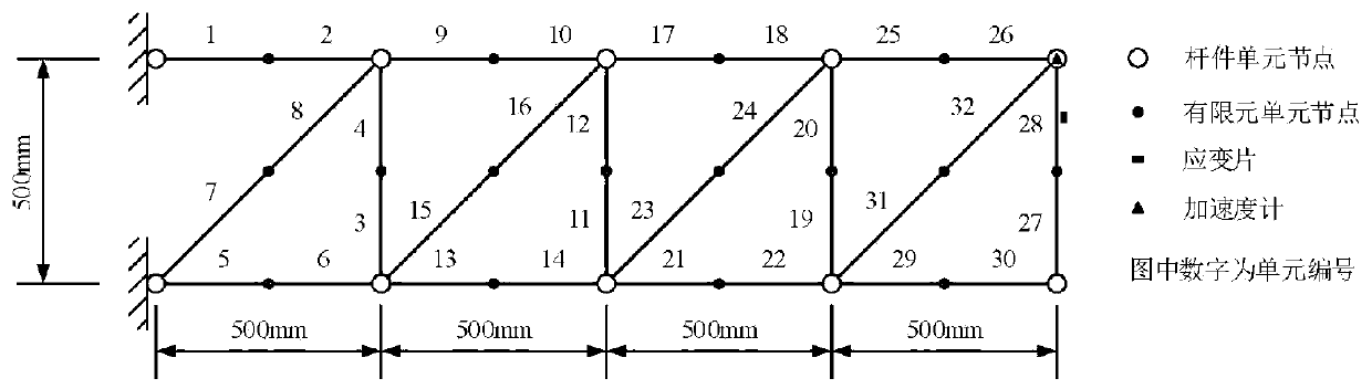
[0019] The truss structure consists of 10 nodes and 16 rods, including 4 upper chord rods, 4 lower chord rods, 4 web rods, each with a length of 500mm, and 4 diagonal web rods with a length of 707mm. 1.5mm thick hollow steel pipe. Create in ABAQUS such as image 3 For the 2D truss model shown, the elastic modulus of the section and Poisson's ratio are set to 210 GPa and 0.3, respectively, and the beam model is used for the members.

[0020] In order to consider the weakening of the stiffness of the member, another section property can be established. The geometric properties of this section are the same as those of the other sections of the original structure, and the stiffness is considered to be 0.5 times that of the other sections to characterize the damage of the member.

[0021] When dividing the mesh for the structure,


PUM


Abstract

The invention discloses a technology for simultaneously identifying rigidity and axial force of a truss structure based on MATLAB-ABAQUS interaction conditions to evaluate structural damage and predict residual bearing capacity, belongs to the field of structural damage identification. The technology mainly comprises the following four steps: establishing a finite element model of a steel truss damage structure; modifying the inp file and establishing a finite element template file; inputting a real to-be-identified quantity and generating an inp file, and calculating and obtaining a corresponding node acceleration and rod strain; simulating the estimated response of the quantity to be identified; and continuously optimizing the to-be-identified quantity by using the target function untila convergence condition is met, and outputting a final result. The method has the main advantages that (1) while the rigidity of a certain rod piece of the steel truss is recognized, the axial force of the same rod piece can also be recognized; (2) the position of the sensor has no special requirement, and the sensor is not required to be installed on a rod piece needing axial force identification; and (3) the number of sensors is less. Therefore, the application prospect of the method is wide.

Description


Claims


Application Information

Patent Timeline
Owner BEIJING UNIV OF TECH
Why Eureka
Try Eureka