Sewage treatment device
A technology of sewage treatment device and driving device, which is applied in the fields of water/sewage multi-stage treatment, biological water/sewage treatment, water/sludge/sewage treatment, etc. Ease of setup, reduced footprint, increased applicability
- Summary
- Abstract
- Description
- Claims
- Application Information
AI Technical Summary
Problems solved by technology
Method used
Image

Examples
Embodiment 1
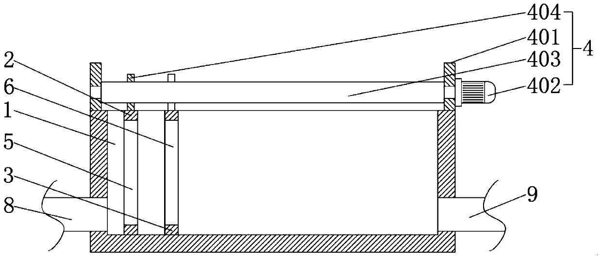
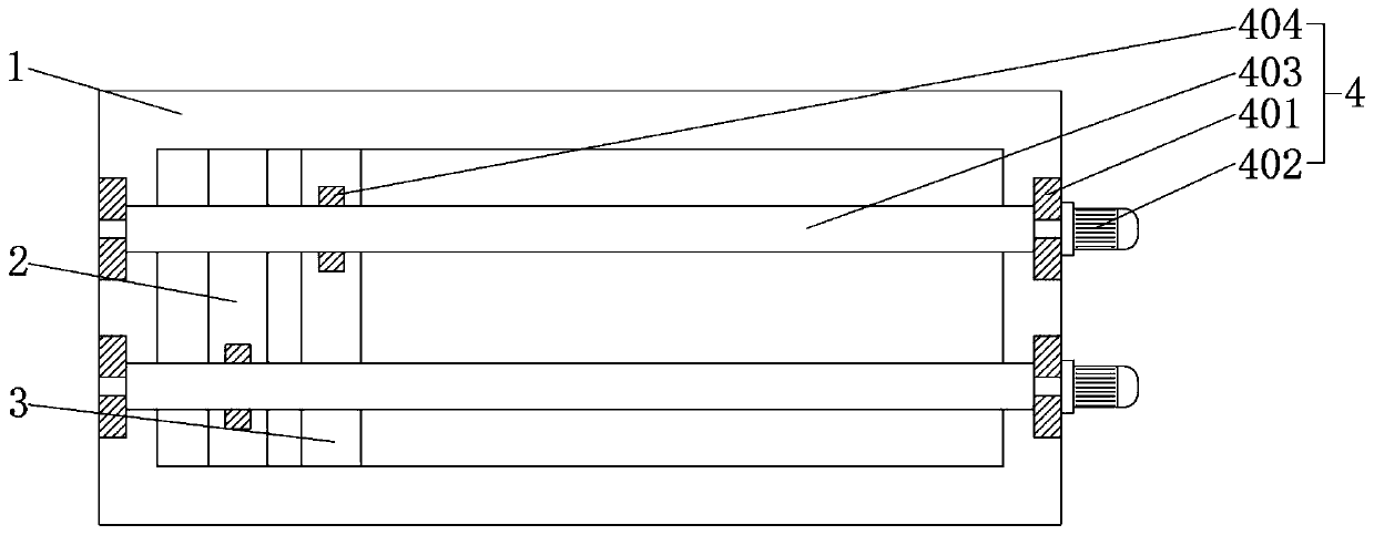
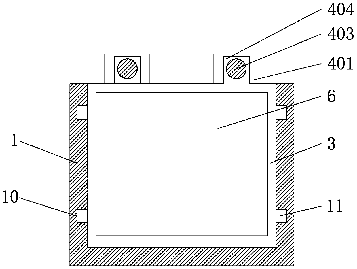
[0025] see Figure 1-3 , the present invention provides a technical solution: a sewage treatment device, comprising a reservoir 1, such as figure 1 As shown, the storage tank 1 is rectangular, and the storage tank 1 of different shapes can also be replaced according to actual needs. The storage tank 1 can be arranged below the ground, so as to save space and facilitate viewing of the storage tank 1 The inner side of the reservoir 1 is respectively provided with a first partition 2 and a second partition 3 that can slide along the extending direction of the reservoir 1, such as image 3 As shown, the size of the first partition 2 and the second partition 3 is the same as the size of the internal chamber section of the reservoir 1, so as to ensure that the first partition 2 and the second partition The outer surfaces of 3 can be in close contact with the inner side walls of the reservoir 1, so that the sewage in the reservoir 1 cannot be separated from the first partition 2 and th
Embodiment 2
[0030] see Figure 4-5 , the difference between this embodiment and embodiment 1 is: as Figure 5 As shown, the end surfaces of the first partition 2 and the second partition 3 are respectively provided with a plurality of through holes 7, and the filter grid 5 and the biofilm layer 6 are respectively arranged in the through holes. 7, so that the first partition 2 and the second partition 3 have good strength, the sewage flows in through the through hole 7, thereby being carried out by the filter grid 5 and the biofilm layer 6 deal with.
[0031] Specifically, the driving device 4 includes a hydraulic push rod 405, the storage tank 1 is close to the side wall of the filter grid 5 and between the filter grid 5 and the storage tank 1 is close to the Hydraulic push rods 405 are respectively provided between the side wall of the biofilm layer 6 and the biofilm layer 6, because the biofilm layer 6 and the filter grid 5 are arranged on the first through the through hole 7. On the pa
PUM
 Abstract
Description
Claims
Application Information
 - R&D Engineer
- R&D Manager
- IP Professional
- Industry Leading Data Capabilities
- Powerful AI technology
- Patent DNA Extraction
Browse by: Latest US Patents, China's latest patents, Technical Efficacy Thesaurus, Application Domain, Technology Topic.
© 2024 PatSnap. All rights reserved.Legal|Privacy policy|Modern Slavery Act Transparency Statement|Sitemap