Clay sculpture cotton mud manufacturing equipment
A cotton and equipment technology, which is applied to the field of clay plastic cotton mud production equipment, can solve the problems of complicated operations, low efficiency, time-consuming and laborious manual mixing, etc. for adding cotton and mixing cement back and forth, so as to save working steps, easy to operate, and simple in structure. Effect
- Summary
- Abstract
- Description
- Claims
- Application Information
AI Technical Summary
Problems solved by technology
Method used
Image

Examples
Embodiment 1
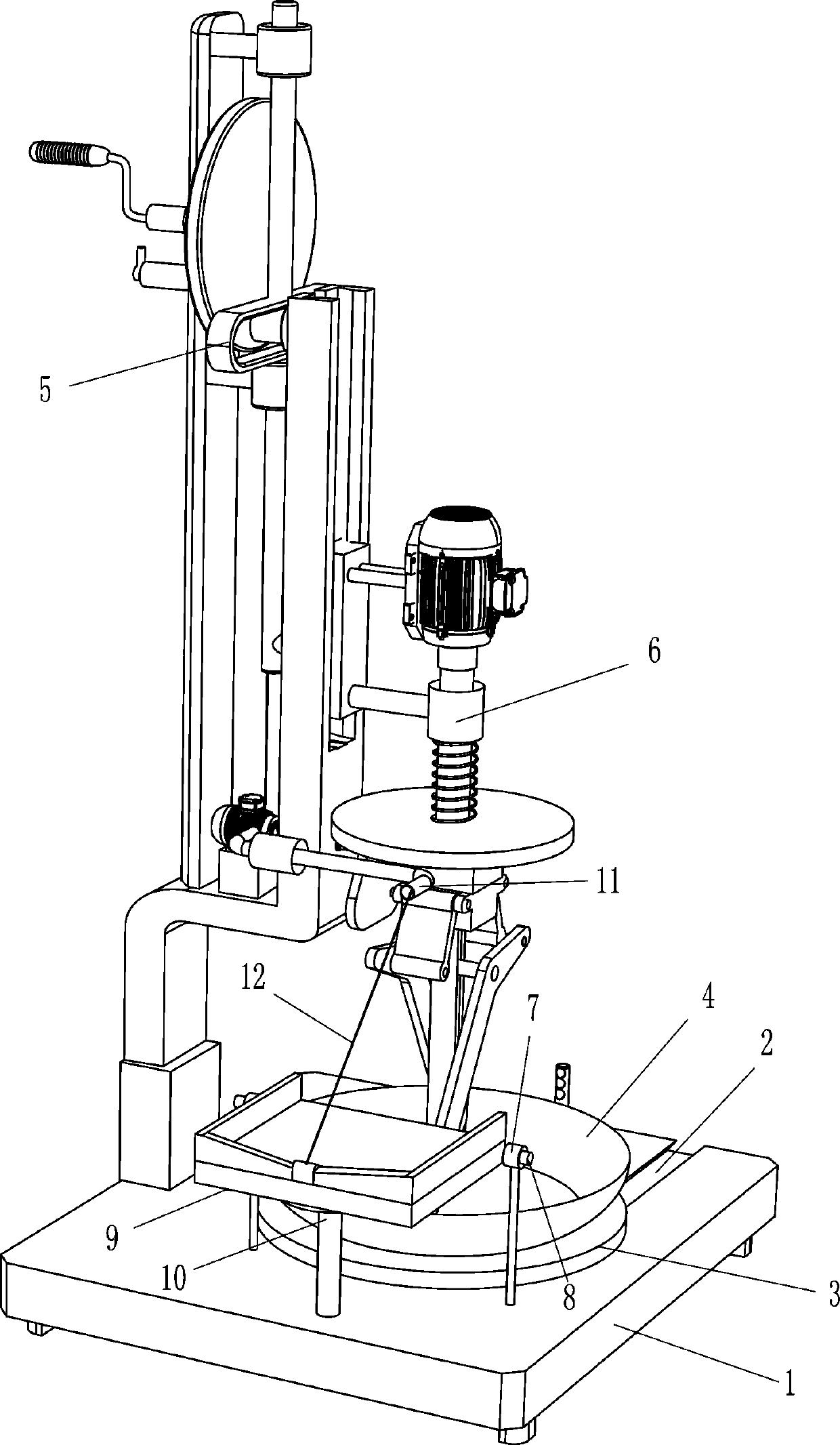
[0021] Such as Figure 1-4 As shown, a clay sculpture cotton mud production equipment includes a base 1, a placing plate 3, a mixing basin 4, a lifting adjustment device 5 and a stirring device 6, and the right side of the top of the base 1 is symmetrically opened with a straight chute 2, and the straight chute 2 The upper sliding type is provided with a placement plate 3, the placement plate 3 is provided with a mixing basin 4, the rear side of the top of the base 1 is provided with a lifting adjustment device 5, and the lifting adjustment device 5 is provided with a stirring device 6.
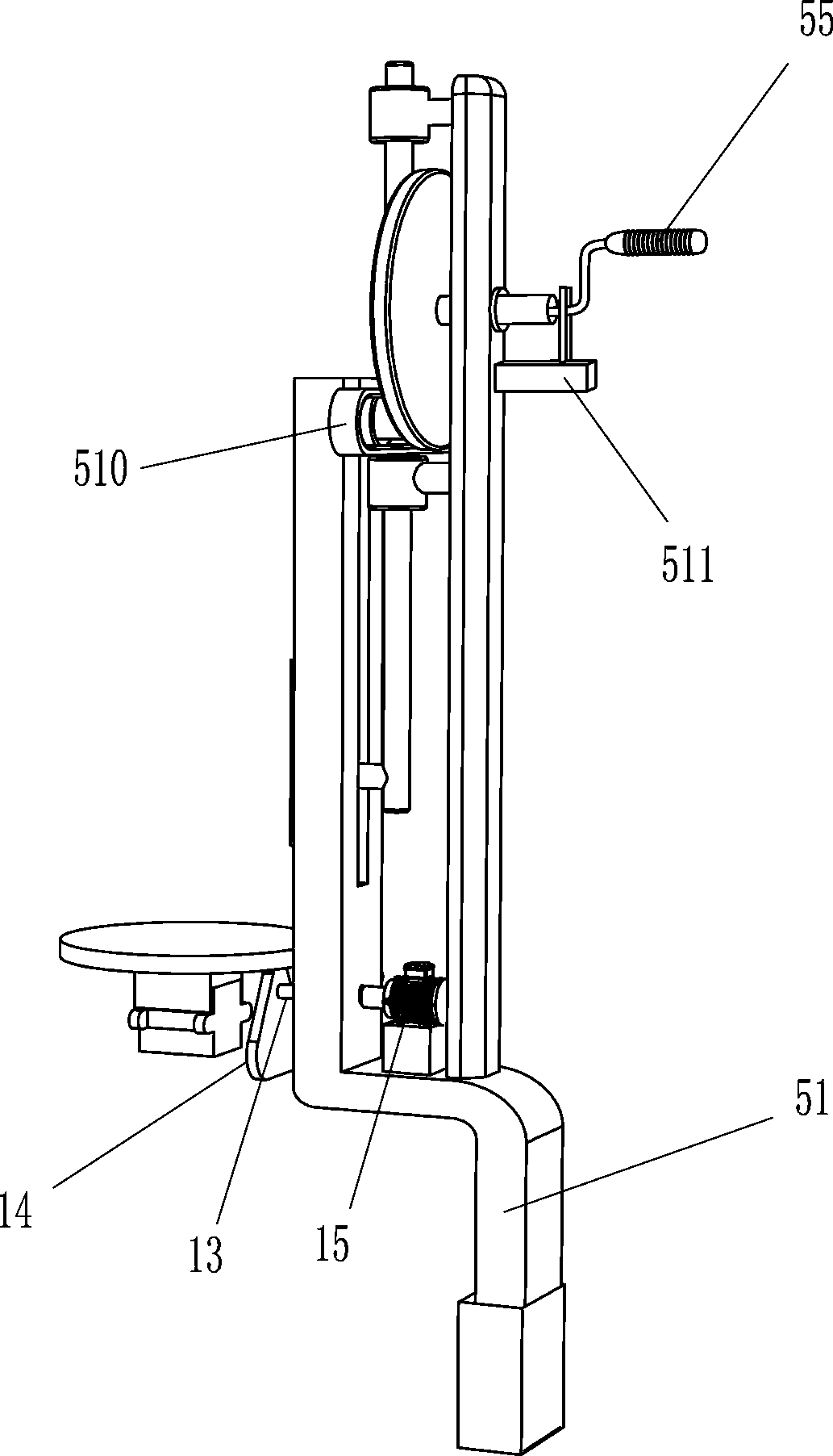
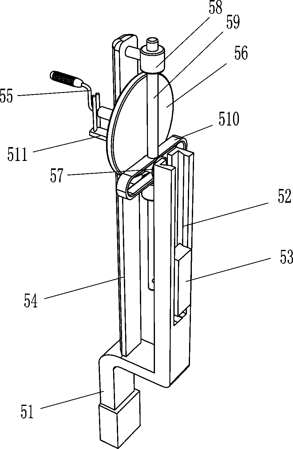
[0022] The lifting adjustment device 5 includes a special-shaped frame 51, a straight slide block 53, a mounting plate 54, a rocking bar 55, a rotating disk 56, a slide shaft 57, a guide sleeve 58, a lifting rod 59, a return-shaped guide groove plate 510 and a card frame insertion rod 511 , the rear side of the top of the base 1 is provided with a special-shaped frame 51, the top of the special-
Embodiment 2
[0026] On the basis of Example 1, such as figure 1 with 4 As shown, it also includes a second bearing seat 7, a second rotating shaft 8, an overturning basin 9, a support plate 10, a wire conduit 11 and a stay rope 12, and the left side of the top of the base 1 is provided with a second bearing seat 7 symmetrically front and back, and the two second Two bearing seats 7 are provided with a second rotating shaft 8, an overturning basin 9 is arranged between the two second rotating shafts 8, a support plate 10 is provided on the left side of the top of the base 1 to support the center of the overturning basin 9, and a special-shaped frame 51 The middle part of the left side wall is provided with a conduit 11, and the middle part of the left wall of the flip basin 9 is provided with a stay cord 12, and the stay cord 12 passes through the conduit 11 and is connected to the bottom of the elevating rod 59 on the downside. During the stirring process, the staff can place the cotton that
PUM
 Abstract
Description
Claims
Application Information
 - R&D Engineer
- R&D Manager
- IP Professional
- Industry Leading Data Capabilities
- Powerful AI technology
- Patent DNA Extraction
Browse by: Latest US Patents, China's latest patents, Technical Efficacy Thesaurus, Application Domain, Technology Topic.
© 2024 PatSnap. All rights reserved.Legal|Privacy policy|Modern Slavery Act Transparency Statement|Sitemap