Antenna near-field rapid measurement method

A measurement method and antenna technology, applied in directions such as antenna radiation patterns, can solve the problem of small improvement in measurement efficiency, and achieve the effects of shortening measurement time, good radiation reconstruction effect, and improving measurement efficiency

Inactive Publication Date: 2020-07-14
HEFEI NORMAL UNIV
View PDF5 Cites 0 Cited by
  • Summary
  • Abstract
  • Description
  • Claims
  • Application Information

AI Technical Summary

Benefits of technology

This patented device uses an array made up of two different materials that are placed next to each other at certain distances from one another for better performance or reduced size. By adjusting these arrangements, it allows signals transmitted through them to have specific properties like resonance frequency (F) or polarization directionality. These modifications help improve signal quality and reduce interference with neighboring devices.

Problems solved by technology

Technological Problem: Highly precise and efficient testing for antennas used in electronic devices such as radar systems or communication equipment involves acquiring signals from multiple sources over different distances while minimally affecting their quality by reducing the amount of collected data needed compared to traditional techniques like measuring single points.

Method used


Image

  • Antenna near-field rapid measurement method
  • Antenna near-field rapid measurement method
  • Antenna near-field rapid measurement method

Examples


Embodiment Construction

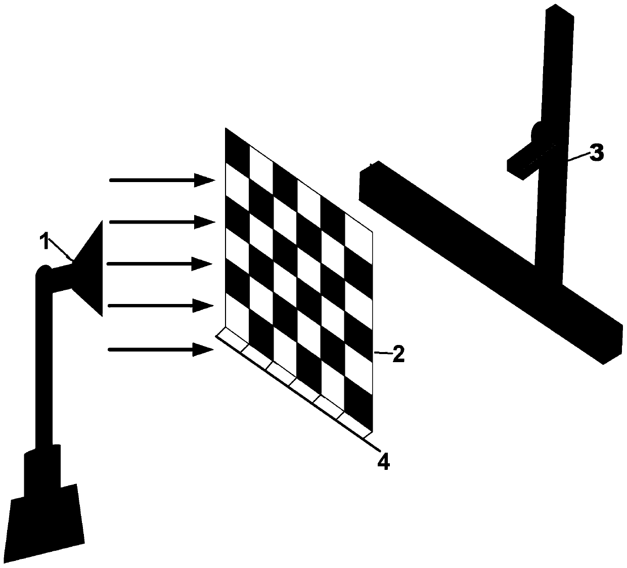
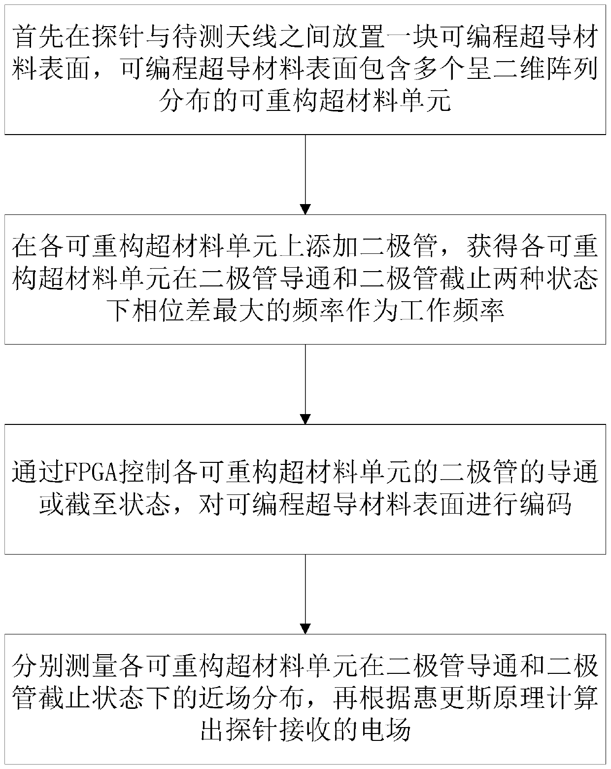
[0034] refer to figure 1 , an antenna near-field fast measurement system proposed by the present invention, including FPGA, programmable metamaterial surface and probe. The probe is set on one side of the programmable metamaterial surface, and the other side of the programmable metamaterial surface is used to place the antenna to be tested.

[0035] The programmable metamaterial surface contains multiple reconfigurable metamaterial units distributed in a two-dimensional array.

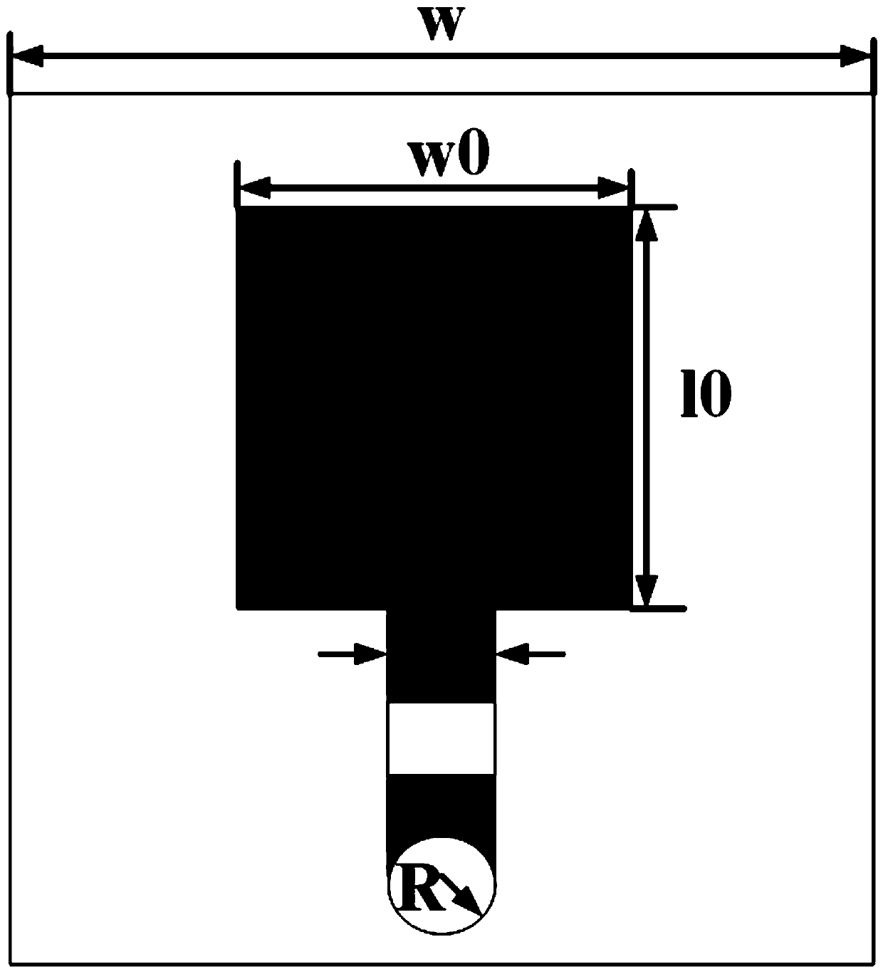
[0036] Reconfigurable metamaterial units, including substrates, metal vias, and diodes. In this way, each reconfigurable metamaterial unit is loaded with a diode, and the state of the reconfigurable metamaterial unit is controlled by turning on and off the diode, that is, the state of the reconfigurable metamaterial unit is controlled by controlling the bias voltage of the diode.

[0037] The FPGA controls the on-off of the diodes in each reconfigurable metamaterial unit, so that the reconfigurable unit


PUM

PropertyMeasurementUnit
Thicknessaaaaaaaaaa

Abstract

The invention provides an antenna near-field rapid measurement system. The system comprises an FPGA, a programmable meta-material surface and a probe. The surface of the programmable meta-material isplaced between the probe and the antenna to be tested; the surface of the programmable meta-material comprises a plurality of reconfigurable meta-material units which are distributed in a two-dimensional array; a diode is loaded on each reconfigurable meta-material unit; the FPGA encodes the surface of the programmable meta-material by controlling the on-off of the diodes in the reconfigurable meta-material units; and the probe acquires near-field data of the to-be-measured antenna which penetrates through the surface of the programmable meta-material, and reconstructs a signal of the to-be-measured antenna according to the near-field data. According to the invention, the measurement efficiency is greatly improved, the measurement time is shortened, and a good radiation reconstruction effect can be obtained.

Description


Claims


Application Information

Patent Timeline
Owner HEFEI NORMAL UNIV
Why Eureka
Try Eureka