Time acquisition method and device and electronic equipment

An electronic device and acquisition method technology, applied in the electronic field, can solve the problems of inaccuracy and low efficiency of client program acquisition of the current time, and achieve the effect of improving efficiency and accuracy

Pending Publication Date: 2020-07-17
ZHUHAI BAOQU TECH CO LTD
View PDF5 Cites 1 Cited by
  • Summary
  • Abstract
  • Description
  • Claims
  • Application Information

AI Technical Summary

Benefits of technology

This technology allows for accurate timing by analyzing how long each part of data travels through servers at different times during their lifespan without requiring any extra effort or reconfiguration on either side. It achieves that it can improve both speed-up and precision time acquirement compared with traditional methods like timers.

Problems solved by technology

The technical problem addressed by this patented technology relates how efficiently an email server (such as Microsoft Outlook) uses its memory to calculate accurate times when sending emails over different networks with varying speeds.

Method used


Image

  • Time acquisition method and device and electronic equipment
  • Time acquisition method and device and electronic equipment
  • Time acquisition method and device and electronic equipment

Examples


Embodiment Construction

[0042] Embodiments of the present application are described below in conjunction with the accompanying drawings.

[0043] The system architecture and business scenarios of the embodiments of the present application are described below. It should be noted that the system architecture and business scenarios described in this application are for the purpose of more clearly explaining the technical solution of this application, and do not constitute a limitation on the technical solution provided by this application. The evolution of technology and the emergence of new business scenarios, the technical solution provided by this application is also applicable to similar technical problems.

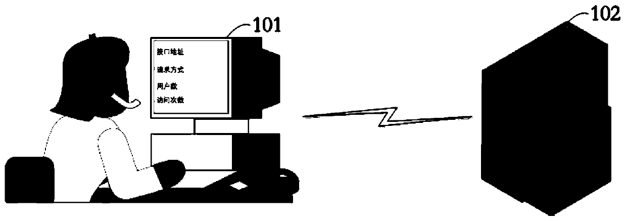
[0044] See figure 1 , figure 1 It is a schematic structural diagram of a time acquisition system provided in the embodiment of the present application. The time acquisition system includes an electronic device 101 and a network server 102, and the time acquisition system is used to acquire a cu


PUM


Abstract

The embodiment of the invention discloses a time obtaining method and device and electronic equipment, and the method comprises the steps: obtaining a system time point of a network server when a client program is detected to be started, and obtaining the first operation time of a local system of the electronic equipment; when it is detected that the client program needs to obtain the current timepoint, obtaining second running time of the local system; and determining the current time point according to the system time point, the first operation time and the second operation time. By adopting the embodiment of the invention, the time acquisition efficiency and accuracy can be improved.

Description


Claims


Application Information

Patent Timeline
Owner ZHUHAI BAOQU TECH CO LTD
Why Eureka
Try Eureka