Adjustable electric automobile wireless charging transmitting device

A wireless charging and transmitting device technology, applied in electric vehicle charging technology, electric vehicles, battery circuit devices, etc., can solve the problems of long distance between power supply coil and receiving coil, low induction magnetic field strength, low charging efficiency, etc.

Pending Publication Date: 2020-07-28
CHONGQING INST OF ENG
View PDF9 Cites 1 Cited by
  • Summary
  • Abstract
  • Description
  • Claims
  • Application Information

AI Technical Summary

Benefits of technology

This patented technology allows vehicles equipped with radios (a type called radio) to communicate without being connected wired or powered up. Instead they use their own batteries instead of relying solely upon battery charges provided by other sources like electric cables. They also have an automatic system where each wheel moves towards its top surface while keeping them level even if there were any obstacles around it. Additionally, this helps improve communication speed and reduces interference during charging compared to traditional methods such as connecting wires. Overall, these technologies enhance safety and convenience for drivers who want to connect cars together more efficiently.

Problems solved by technology

This patented technical problem addressed in this patents relates to improving wireless charger performance when charged underground due to longer inductive force caused by the embedding of the receiver within the road surface nearer the electrical equipment being charged.

Method used


Image

  • Adjustable electric automobile wireless charging transmitting device
  • Adjustable electric automobile wireless charging transmitting device
  • Adjustable electric automobile wireless charging transmitting device

Examples


Embodiment Construction

[0033] In order to enable those skilled in the art to better understand the present invention, the technical solution of the present invention will be further described below in conjunction with the accompanying drawings and embodiments.

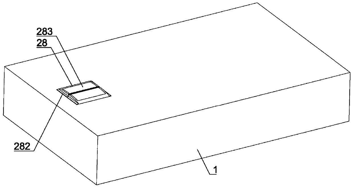
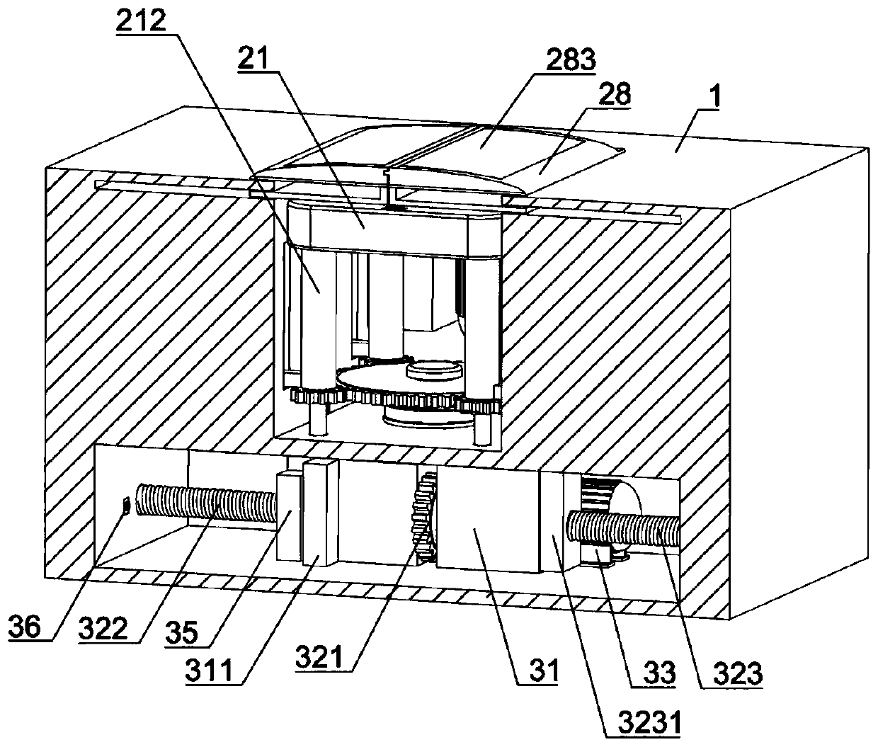
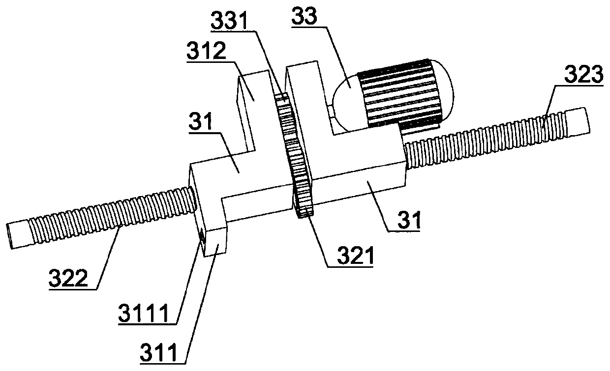
[0034] Such as Figure 1-Figure 8 As shown, an adjustable electric vehicle wireless charging transmitting device of the present invention includes a ground platform 1. The ground platform 1 is provided with an upper chamber 2 and a lower chamber 3. The upper chamber 2 is provided with a lifting mechanism and a wireless charging transmitter. The device 21, the lifting mechanism includes an installation cavity 22, the installation cavity 22 is equipped with a first motor 221, a processing controller 214 is provided on one side of the first motor 221, the first motor 221 rotating shaft is fixedly connected with a driving pulley 222, and the first motor 221 side is provided with the first rotating rod 23, and the first rotating rod 23 is connected


PUM


Abstract

The invention belongs to the technical field of automobile charging, and more specifically relates to an adjustable electric automobile wireless charging transmitting device. The adjustable electric automobile wireless charging transmitting device comprises a ground platform, the ground platform is provided with an upper cavity and a lower cavity. The upper cavity is provided with a lifting mechanism and a wireless charging transmitting device; the lifting mechanism comprises a mounting cavity; a first motor is assembled in the mounting cavity; the first motor is provided with a processing controller, the first motor is connected with a driving belt wheel; a first rotating rod is arranged on one side of the first motor; the first rotating rod is provided with a driven belt wheel; a transmission belt is arranged between the driving belt wheel and the driven belt wheel; the first rotating rod is provided with a first driving gear; the upper cavity is rotationally connected with a secondrotating rod; the second rotating rod is provided with a first driven gear, the first driven gear is connected with a lead screw, the wireless charging transmitting device is provided with a distancesensor, the wireless charging transmitting device is connected with a threaded sleeve, a limiting sliding groove is provided with a first limiting controller, the upper cavity is provided with a firstsliding groove, the first sliding groove is slidably connected with a protective cover plate, and the lower cavity is provided with a sliding mechanism.

Description


Claims


Application Information

Patent Timeline
Owner CHONGQING INST OF ENG
Why Eureka
Try Eureka