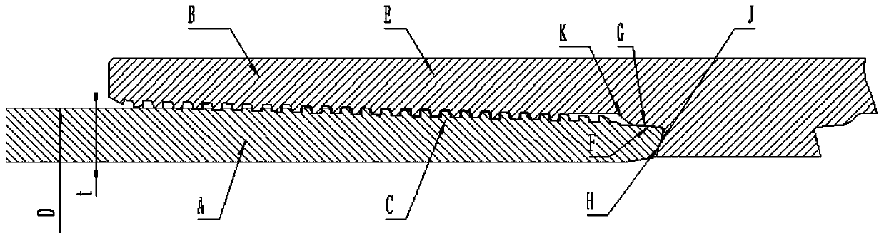
Gas seal threaded joint structure suitable for SAGD thermal production well pipe column connection
A threaded joint and hermetic sealing technology, which is applied in the direction of drilling pipes, casings, and mining fluids, can solve the problems of reduced contact pressure on the sealing surface, loss of sealing ability, shortened contact length of the sealing surface, etc., and achieves excellent sealing integrity. Effect
- Summary
- Abstract
- Description
- Claims
- Application Information
AI Technical Summary
Problems solved by technology
Method used
Image

Examples
Embodiment 1
[0059] The outer diameter D=219.08mm, wall thickness t=8.94mm casing.
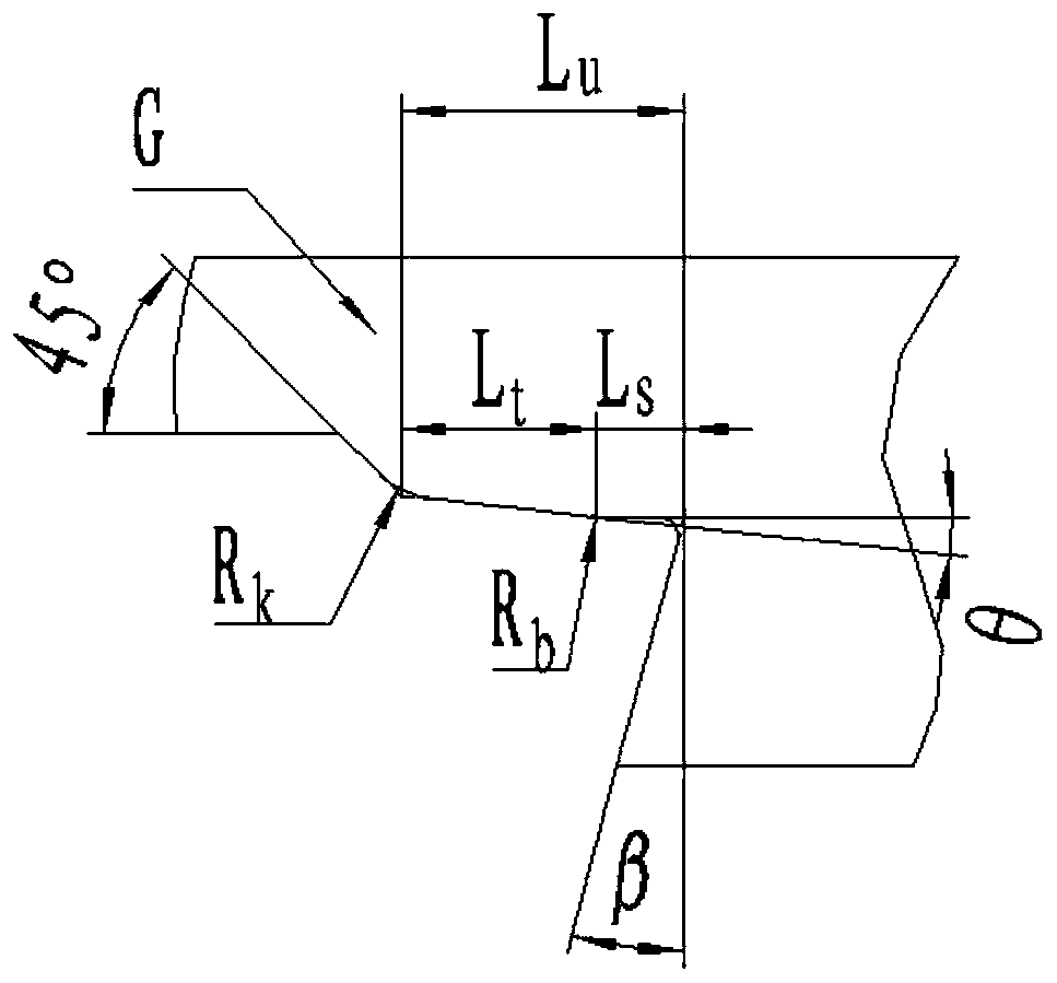
[0060] The data of the sealing surface of the female end are as follows: According to the range of θ in formula 1, determine θ=3°. According to formula 2, determine the rounding angle between the conical surface and cylindrical surface of the female sealing surface as R b = 5mm. Calculated according to formula 3 to get L u The range is 10.95 ~ 19.17mm, determine the L u = 15 mm. Calculated according to formula 5 to get L s The range is 2.25 ~ 3.75mm, determine the L s = 3 mm. According to formula 4 calculation can get L t =15-3=12mm. Determine R according to Equation 6 k = 5mm.
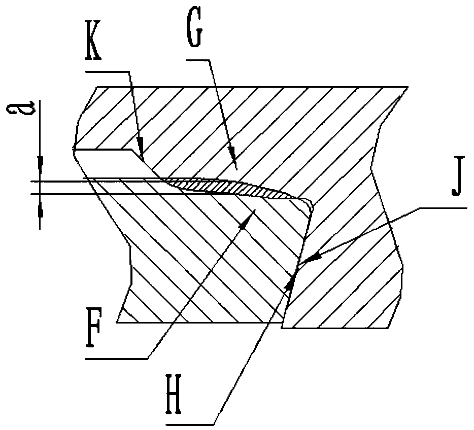
[0061] The data of the sealing surface of the male end are as follows: L is calculated according to formula 7 e The range is 15 ~ 19.5mm, determine the L e =17mm. The range of calculating a according to formula 9 is: 0.26≤a≤0.42mm, and a=0.3mm is determined. Calculated according to Formula 10, the range of the radius R
Embodiment 2
[0064] The outer diameter of specification D=244.48mm, the casing of wall thickness t=10.03mm.
[0065] The data of the sealing surface of the female end are as follows: According to the range of θ in formula 1, determine θ=10°. According to formula 2, determine the rounding angle between the conical surface and cylindrical surface of the female sealing surface as R b = 5mm. Calculated according to formula 3 to get L u The range is 12.22 ~ 21.39mm, determine the L u = 16 mm. Calculated according to formula 5 to get L s The range is 2.4 ~ 4mm, determine the L s = 3.2 mm. According to formula 4 calculation can get L t =16-3.2=12.8mm. Determine R according to Equation 6 k = 6 mm.
[0066] The data of the sealing surface of the male end are as follows: L is calculated according to formula 7 e The range is 16 ~ 20.8mm, determine the L e = 18.5 mm. The range of calculating a according to formula 9 is: 0.25≤a≤0.42mm, and a=0.33mm is determined. Calculated according to form
PUM
 Abstract
Description
Claims
Application Information
 - R&D Engineer
- R&D Manager
- IP Professional
- Industry Leading Data Capabilities
- Powerful AI technology
- Patent DNA Extraction
Browse by: Latest US Patents, China's latest patents, Technical Efficacy Thesaurus, Application Domain, Technology Topic.
© 2024 PatSnap. All rights reserved.Legal|Privacy policy|Modern Slavery Act Transparency Statement|Sitemap