Letter box device

A letter box and sliding joint technology, applied in packaging, transportation and packaging, paper/cardboard containers, etc., can solve the problems of uneven extrusion force, waste of manpower and material resources, inconvenient use, etc., to achieve convenient and quick removal and increase work. Efficiency, simple and convenient operation

Inactive Publication Date: 2017-08-22
岑浩明
View PDF0 Cites 0 Cited by
  • Summary
  • Abstract
  • Description
  • Claims
  • Application Information

AI Technical Summary

Benefits of technology

This patented technology allows for easy removal or replacement of an enclosed space called the mailroom by inserting a watermark into the wall behind the mailpiece without causing damage during installation. It simplifies construction processes while maintaining durability over time. Additionally, this design prevents the mailcase's contents being damaged because there was insufficient pressure applied between its internal parts after assembly. Overall, these technical features improve the functionality and usable life span of the mailer door panels used in building materials such as housewares.

Problems solved by technology

Technically speaking, current printing techniques involve creation of customized letters by adding special marks onto certain parts or areas in order for them to communicate properly during printing process. However, these processes can result in wasted materials due to imperfections caused by previous designs that were added later without being noticeable through visual inspection. Therefore there exists an issue where traditional ways of making printed documents have limitations like slow productivity, imprecise design, lack of flexibility, difficulty in removing postage stamps from the final products, etc., leading to reduced quality control over finished prints made up of multiple layers of labels.

Method used


Image

  • Letter box device
  • Letter box device
  • Letter box device

Examples


Embodiment Construction

[0021] The preferred embodiments of the present invention will be described in detail below in conjunction with the accompanying drawings, so that the advantages and features of the present invention can be more easily understood by those skilled in the art, so as to define the protection scope of the present invention more clearly.

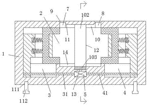
[0022] refer to Figure 1-5 A letterbox device shown includes an outer frame 1, and the bottom of the outer frame 1 is provided with an inner screw hole 111, and a bolt column 112 is arranged in the inner screw hole 111, and the bolt column 112 can be moved up and down. adjustment, so as to facilitate the arrangement of the device on uneven ground, the outer frame 1 is provided with a left and right empty slot 2, and the left and right ends of the bottom of the empty slot 2 are respectively provided with left sliding slots 3 and the right sliding connection groove 4, the outer frame 1 between the left sliding connecting groove 3 and the right slidin


PUM


Abstract

The invention discloses a letter box device which comprises an outer frame. An inner screw joint hole is formed in the bottom of the outer frame. A bolt column is arranged in the inner screw joint hole in a matched mode. An empty groove expanded left and right is formed inside the outer frame. A left sliding connection groove and a right sliding connection groove are equally formed in the left and right ends of the bottom end of the empty groove. A first electric motor is arranged in the portion, between the left sliding connection groove and the right sliding connection groove, of the outer frame. A left screw joint rod and a right screw joint rod are equally arranged in the left sliding joint groove and the right sliding joint groove respectively. A left extrusion element and a right extrusion element are arranged on the left screw joint rod and the right screw joint rod in a matched mode respectively. The letter box device is simple in structure, low in production cost and easy and convenient to operate, the working efficiency of extrusion and molding of a letter box panel is greatly improved, waste of manpower and material resources is reduced, the extruded and molded letter box panel is firm and reliable and can be taken down conveniently and rapidly, and the flatness and the attractiveness of the letter box panel are effectively improved.

Description


Claims


Application Information

Patent Timeline
Owner 岑浩明
Why Eureka
Try Eureka