Light leakage brightness detection system and detection method thereof
A technology of brightness detection and detection method, applied in optics, nonlinear optics, instruments, etc., can solve the problem of inability to measure the brightness value of dark state light leakage in the micro-area of TFT-LCD sub-pixels, and achieve the effect of easy detection.
- Summary
- Abstract
- Description
- Claims
- Application Information
AI Technical Summary
Problems solved by technology
Method used
Image

Examples
Example Embodiment
[0033] Example 1
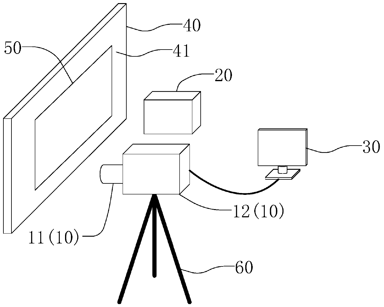
[0034] The embodiment of the present invention provides a light leakage brightness detection system, such as figure 1 As shown, the light leakage brightness detection system includes an optical imaging device 10, a brightness measuring instrument 20, a data processor 30, and a backlight 40.
[0035] The backlight source 40 has a light-emitting surface 41, the optical imaging device 10 and the brightness measuring instrument 20 are arranged on the side of the backlight source 40 close to the light-emitting surface 41, and the optical imaging device 10 and the light-emitting surface 41 The brightness measuring instruments 20 all face the light emitting surface 41 of the backlight source 40. The backlight source 40 is used to provide a light source for the detected object.
[0036] The optical imaging device 10 is fixed on one side of the backlight source 40 through a bracket 60, and includes a camera 12 and a microscope 11. The camera 12 may be a single-lens reflex ca
Example Embodiment
[0049] Example 2
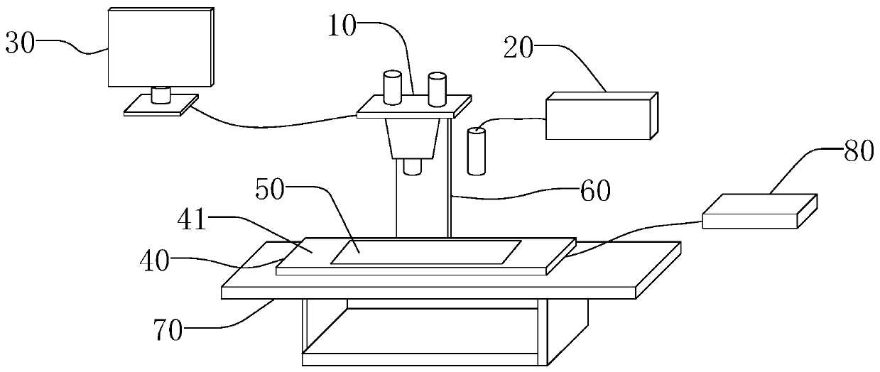
[0050] The embodiment of the present invention provides a light leakage brightness detection system, such as figure 2 As shown, the light leakage brightness detection system includes an optical imaging device 10, a brightness measuring instrument 20, a data processor 30, and a backlight 40.
[0051] The light leakage brightness detection system also has a carrier 70, and the backlight source 40 is arranged on the carrier 70 and connected to a power supply 80. The backlight source 40 has a light emitting surface 41, and a surface of the backlight source 40 away from the light emitting surface 41 is in contact with the table surface of the carrier 70. The optical imaging device 10 and the brightness measuring instrument 20 are arranged on the side of the backlight source 40 close to its light-emitting surface 41, and the optical imaging device 10 and the brightness measuring instrument 20 are both facing the backlight source 40 The luminous surface 41. The backligh
Example Embodiment
[0057] Example 3
[0058] An embodiment of the present invention provides a detection method of a light leakage brightness detection system, which can use the light leakage brightness detection system provided in Embodiment 1 or Embodiment 2 for detection, which includes the following steps:
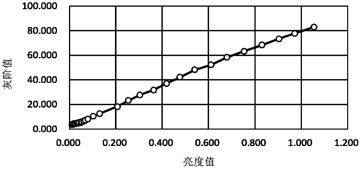
[0059] Obtain the brightness value of each color zone in the grayscale test card 50: use a brightness tester to measure the brightness of each color zone in the grayscale test card 50, obtain the calibrated brightness value of each color zone, and then use the obtained calibrated brightness value Input to the data processor 30.
[0060] Form the corresponding relationship between the grayscale value and the brightness value: the obtained calibration grayscale value and the calibration brightness value are processed by the data processor 30, and the corresponding relationship between the grayscale value and the brightness value is obtained, and the corresponding relationship is drawn The graph of
PUM
 Abstract
Description
Claims
Application Information
 - R&D Engineer
- R&D Manager
- IP Professional
- Industry Leading Data Capabilities
- Powerful AI technology
- Patent DNA Extraction
Browse by: Latest US Patents, China's latest patents, Technical Efficacy Thesaurus, Application Domain, Technology Topic.
© 2024 PatSnap. All rights reserved.Legal|Privacy policy|Modern Slavery Act Transparency Statement|Sitemap