Lamp remote debugging system and lamp debugging method

A technology for remote debugging and lighting. It is used in the testing of optical performance, optical instrument testing, and testing of machine/structural components. It can solve problems affecting the debugging efficiency of lamps, and achieve the effect of improving test efficiency and reasonable structure

Pending Publication Date: 2020-08-21
SHENZHEN EX LIGHTING TECH HLDG
View PDF5 Cites 0 Cited by
  • Summary
  • Abstract
  • Description
  • Claims
  • Application Information

AI Technical Summary

Problems solved by technology

[0003] In the existing technology, on-site debugging requires the cooperation of two people, that is, one person is watching the effect downstairs, and the other is switching the test effect on the roof. The two parties communicate by phone, which seriously affects the debugging efficiency of the lamps.

Method used


Image

  • Lamp remote debugging system and lamp debugging method
  • Lamp remote debugging system and lamp debugging method
  • Lamp remote debugging system and lamp debugging method

Examples


Example Embodiment

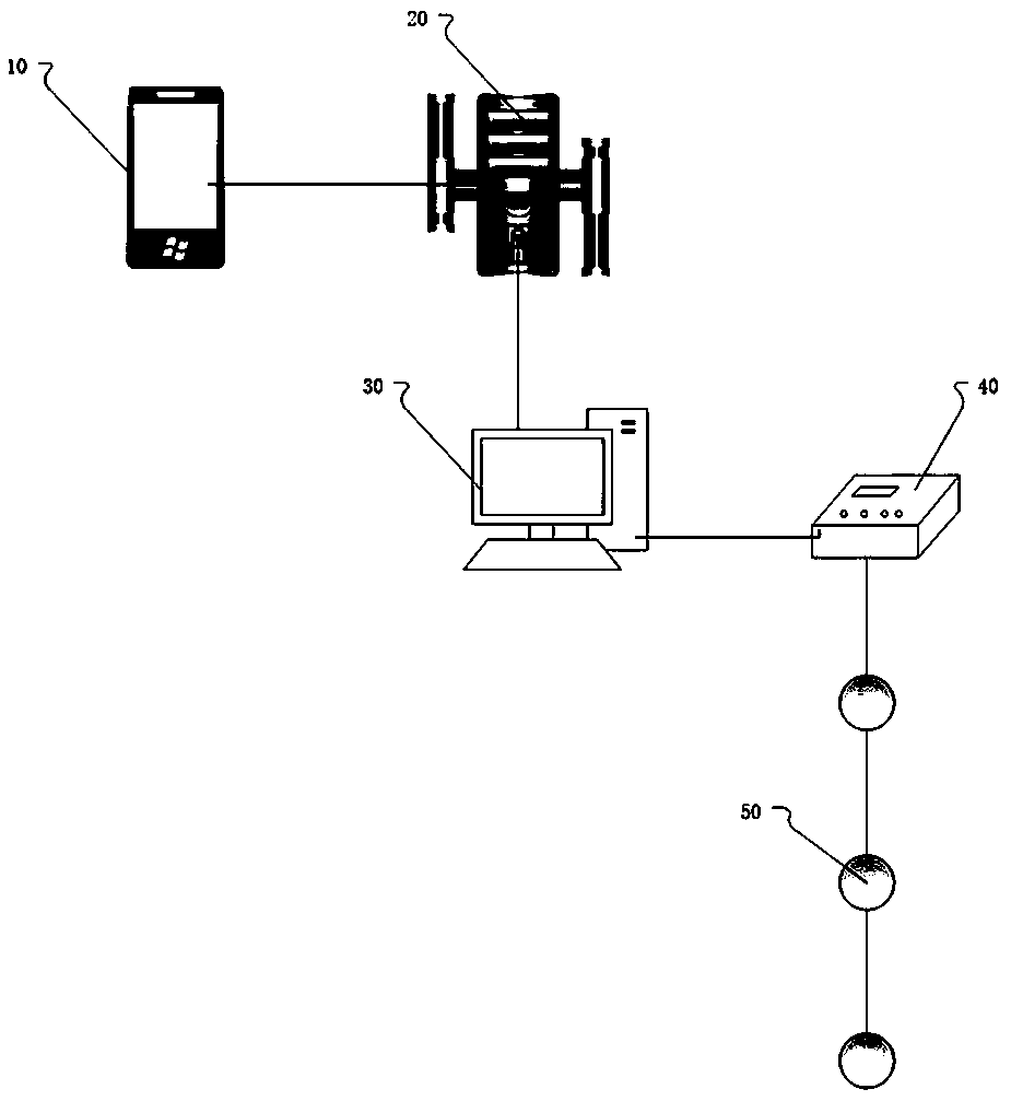
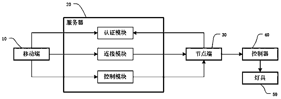
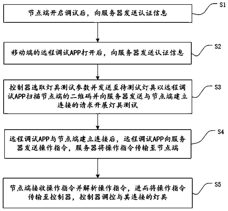
[0026] Figure 1 to Figure 3 It is a related schematic diagram of a remote debugging system and a method for debugging a lamp described in this application. The present invention will be described in detail below with reference to specific embodiments and drawings.

[0027] The embodiments described here are specific specific implementations of the present invention, which are used to illustrate the concept of the present invention. They are all explanatory and exemplary, and should not be construed as limiting the embodiments of the present invention and the scope of the present invention. In addition to the implementation exceptions described here, those skilled in the art can also adopt other obvious technical solutions based on the content disclosed in the claims and specification of this application. These technical solutions include adopting any obvious changes to the embodiments described herein. Technical solutions for replacement and modification.

[0028] The drawings in th


PUM


Abstract

The invention discloses a lamp remote debugging system and a lamp debugging method. The lamp remote debugging system comprises a mobile terminal, a server, a node terminal and a controller, the mobileterminal is connected to the server, the server is connected to the node terminal, and the node terminal is connected to the controller to control the test of a lamp; the server comprises an authentication module, a connection module and a control module; the mobile terminal acquires control information by scanning a two-dimensional code and sends a connection request to the server, a connectionmodule of the server establishes connection with the node terminal, and the node terminal acquires a control instruction through the control module of the server so as to control the test of the lampthrough the controller. The lamp remote debugging system and the lamp debugging method provided by the invention are suitable for testing intelligent lamps like LED lamps, the structure is reasonable,remote lamp debugging is realized, and the lamp testing efficiency is effectively improved.

Description


Claims


Application Information

Patent Timeline
Owner SHENZHEN EX LIGHTING TECH HLDG
Why Eureka
Try Eureka