Metal plate bending machine automatic feeding device and working method thereof

An automatic feeding and bending machine technology, applied in the direction of feeding device, positioning device, storage device, etc., can solve the problems of waste of resources, cost a lot of manpower and material resources, etc., and achieve the effect of firm and stable grasping

Inactive Publication Date: 2020-09-29
商兆惠
View PDF0 Cites 0 Cited by
  • Summary
  • Abstract
  • Description
  • Claims
  • Application Information

AI Technical Summary

Benefits of technology

This technology allows for better control over how well an image forming device works by allowing certain parts or components within it to move around freely without interferring with other movements. It also includes features like grip mechanisms at both ends of each shift lever, which helps keep them steady during use while still being able to hold various size paper products securely.

Problems solved by technology

This patented technical problem addressed by this patents relates to improving the efficiency and accuracy of machining sheets with bent parts during manufacturing processes such as panel production. Traditional methods require manual adjustment after placement onto an ironing plate, which wastes time and materials resource compared to automated systems that corrects errors quickly without requiring excessive human labor costs.

Method used


Image

  • Metal plate bending machine automatic feeding device and working method thereof
  • Metal plate bending machine automatic feeding device and working method thereof
  • Metal plate bending machine automatic feeding device and working method thereof

Examples


Embodiment Construction

[0050] The following will clearly and completely describe the technical solutions in the embodiments of the present invention with reference to the accompanying drawings in the embodiments of the present invention. Obviously, the described embodiments are only some, not all, embodiments of the present invention. Based on the embodiments of the present invention, all other embodiments obtained by persons of ordinary skill in the art without making creative efforts belong to the protection scope of the present invention.

[0051] It should be noted that when a component is said to be "mounted on" another component, it may be directly on the other component or there may be an intervening component. When a component is said to be "set on" another component, it may be set directly on the other component or there may be an intervening component at the same time. When a component is said to be "fixed" to another component, it may be directly fixed to the other component or there may be


PUM


Abstract

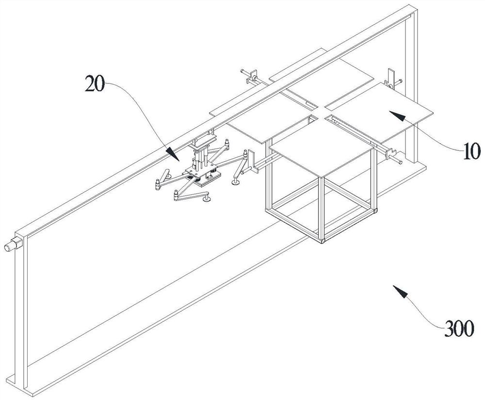
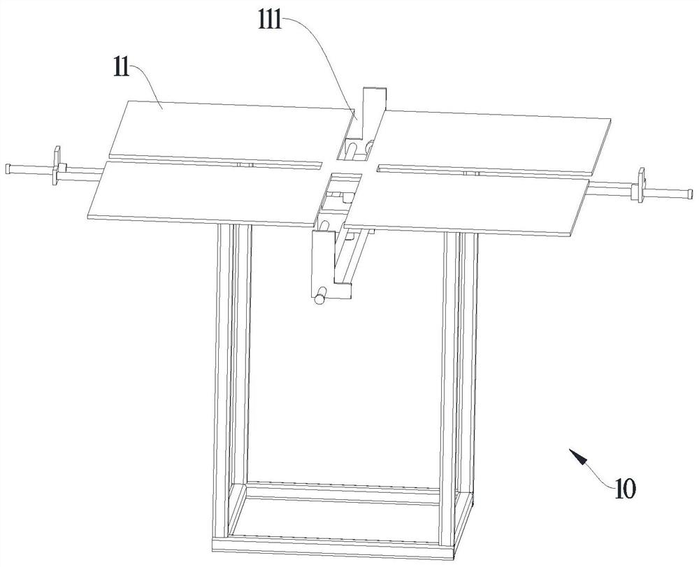
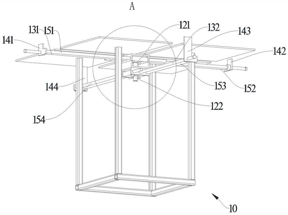
The invention relates to a metal plate bending machine automatic feeding device. The device comprises a plate centering mechanism and a grabbing mechanism, wherein the center line of the plate centering mechanism and the center line of the grabbing mechanism are located in the same vertical plane, and the plate centering mechanism comprises a placement plate, a first motor, a first screw, a firstshifting plate, a second shifting plate, a first sliding rod and a second sliding rod. The technical scheme has the advantages that through the arrangement of the first shifting plate, the second shifting plate, a third shifting plate and a fourth shifting plate, a plate can be positioned, the center lines of the plate centering mechanism and the grabbing mechanism are located in the same verticalplane, and the grabbing mechanism can be connected with the center of the plate when grabbing the plate on the plate centering mechanism, so that grabbing is more stable, the position of a suction cup of the grabbing mechanism can be adjusted, plates of different sizes can be grabbed, and grabbing is firmer.

Description


Claims


Application Information

Patent Timeline
Owner 商兆惠
Why Eureka
Try Eureka