Convenient-rectifying winding device for producing zippers

A technology of a winding device and a zipper, which is applied in the directions of transportation and packaging, thin material handling, and transportation of filamentous materials, can solve the problems of time-consuming and labor-intensive, and reduce production efficiency, and achieve the effect of avoiding entanglement, improving efficiency and facilitating disassembly.

Active Publication Date: 2020-09-29
四会市世经拉链制品有限公司
View PDF6 Cites 2 Cited by
  • Summary
  • Abstract
  • Description
  • Claims
  • Application Information

AI Technical Summary

Benefits of technology

The technical effect described in this patented design relates to an improved winder system for producing zippable pleats or tabs on zippage belts. It includes a wound unit made up of three parts - a supporting part called a mainframe, a moving part called the driving/receiving roller (or guide) rods, and a mechanism where these components work together smoothly during movement along rails inside the machine's framework. By adjusting certain parameters such as position, speed, power supply, etc., different types of zipples may also be produced without compromising their quality. Additionally, there has been developed a wiring assembly for controlling the operation of each component individually, making it easier to fix any issues related to deviations caused by manufacturing tolerances. Overall, this technology provides better control over how well-designed zippled pleat products are formed and processed.

Problems solved by technology

This patented technical problem addressed in this patents relates to improving the manufacturing process of zippers by reducing their complexity while maintaining high quality standards without requiring complicated assembly processes.

Method used


Image

  • Convenient-rectifying winding device for producing zippers
  • Convenient-rectifying winding device for producing zippers
  • Convenient-rectifying winding device for producing zippers

Examples


Embodiment Construction

[0030] The technical solutions in the embodiments of the present invention will be clearly and completely described below in conjunction with the accompanying drawings in the embodiments of the present invention. Obviously, the described embodiments are only some of the embodiments of the present invention, not all of them. Based on The embodiments of the present invention and all other embodiments obtained by persons of ordinary skill in the art without making creative efforts belong to the protection scope of the present invention.

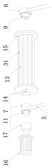
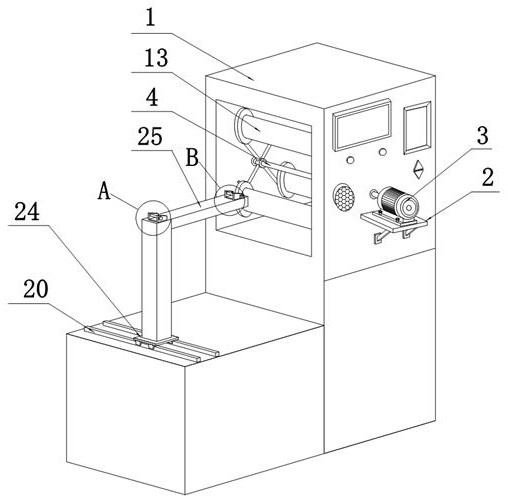
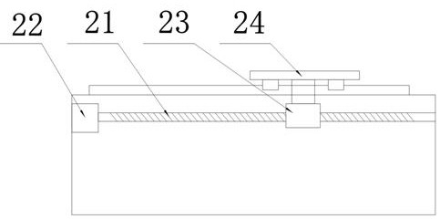
[0031] see Figure 1-6 , the present invention provides a technical solution: a winding device for zipper production that is convenient for deviation correction, including a winding device body 1, a support frame 2 is fixed on one side of the winding device body 1, and a support frame 2 is fixed on the upper surface of the support frame 2. There is a first servo motor 3, one side of the first servo motor 3 is driven with a first rotating shaft 4, a


PUM


Abstract

The invention discloses a convenient-rectifying winding device for producing zippers. The convenient-rectifying winding device comprises a winding device body, a supporting frame is fixedly arranged on the surface of one side of the winding device body, a first servo motor is fixedly arranged on the surface of the upper end of the supporting frame, a first rotary shaft is arranged on one side of the first servo motor in a transmission mode, a plurality of connecting rods are correspondingly and uniformly distributed at the two ends of the first rotary shaft along the circumference, a first bearing is fixed to the connecting rod fixed to one end of the first rotary shaft, and a second bearing is fixed to the connecting rod fixed to the other end of the first rotary shaft. A first sliding telescopic sleeve is fixed to the inner wall of the first bearing, a clamping sleeve is slidably arranged in the first sliding telescopic sleeve, a second sliding telescopic sleeve is fixed to the innerwall of the second bearing, a magnetic clamping shaft is slidably arranged in the second sliding telescopic sleeve, a winding roller is arranged between the second bearing and the clamping sleeve ina sleeving mode, baffles are arranged at the two ends of the winding roller, and the zippers are wound in the baffles. The assembly and disassembly are simple and convenient, the structure is reasonable, the using is safe and convenient, and great help is provided for people.

Description


Claims


Application Information

Patent Timeline
Owner 四会市世经拉链制品有限公司
Why Eureka
Try Eureka