Lubricating oil sealing structure and aircraft engine

An aero-engine and lubricating oil technology, which is applied to engine components, combustion engines, engine cooling, etc., can solve the problem of difficulty in taking into account the floating ring and grate teeth at the same time, difficult to deal with the high temperature and high pressure environment of gas turbine bearings, and interstage boosted bleed air. The structural sealing of the flow path needs to be improved to achieve the effect of preventing oil leakage and improving the secondary sealing effect.

Active Publication Date: 2020-11-13
AECC HUNAN AVIATION POWERPLANT RES INST
View PDF6 Cites 1 Cited by
  • Summary
  • Abstract
  • Description
  • Claims
  • Application Information

AI Technical Summary

Problems solved by technology

Existing single-stage seals are difficult to cope with the high temperature and high pressure environment of gas turbine bearings
Although the two-stage seal is better than the single-stage seal, it is difficult to take into

Method used


Image

  • Lubricating oil sealing structure and aircraft engine
  • Lubricating oil sealing structure and aircraft engine
  • Lubricating oil sealing structure and aircraft engine

Examples


Embodiment Construction

[0054] Typical embodiments embodying the features and advantages of the present invention will be described in detail in the following description. It should be understood that the present invention can have various changes in different embodiments without departing from the scope of the present invention, and that the description and drawings therein are illustrative in nature and not intended to limit the present invention. invention.

[0055]In the following description of various exemplary embodiments of the invention, reference is made to the accompanying drawings, which form a part hereof, and in which are shown by way of example different exemplary structures, systems, and embodiments in which aspects of the invention may be implemented and steps. It is to be understood that other specific arrangements of components, structures, exemplary devices, systems and steps may be utilized and structural and functional modifications may be made without departing from the scope of


PUM

PropertyMeasurementUnit
Widthaaaaaaaaaa
Radial thicknessaaaaaaaaaa

Abstract

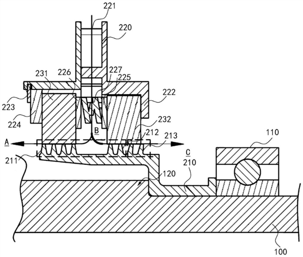
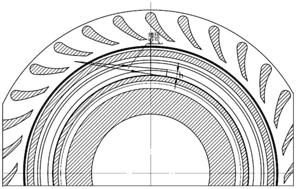
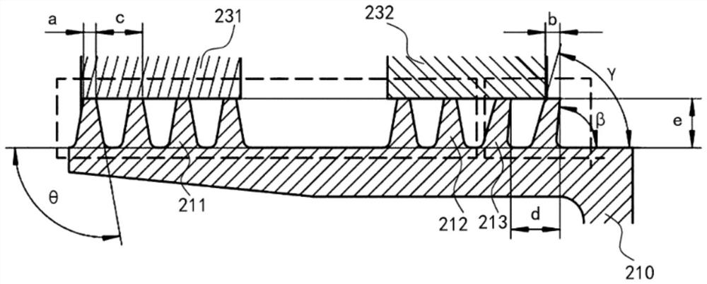
The invention provides a lubricating oil sealing structure and an aircraft engine. The lubricating oil sealing structure comprises a grate tooth ring, a sealing shell and two graphite rings, wherein arotating shaft is sleeved with a grate tooth ring, the grate tooth ring is provided with an outer ring surface, and two groups of grate teeth are axially arranged at intervals front and back around the outer ring surface; the sealing shell is arranged around the periphery of the grate tooth ring and is provided with an axial positioning assembly, and the sealing shell is provided with a pre-rotating blade runner; the two graphite rings are respectively sleeved between the grate tooth ring and the sealing shell, are axially arranged front and back in a spaced mode, and respectively correspondto the two groups of grate teeth in a clearance fit mode, the two graphite rings are axially positioned through the axial positioning assembly, and the two graphite rings are of a floating ring structure; and the lubricating oil sealing structure is configured so that external air flow sequentially flows through the pre-rotating blade runner, the gap between the two graphite rings, the gap betweenthe two groups of grate teeth and the gap between the two graphite rings and the two groups of grate teeth and then respectively flows to the spaces on the front side and the rear side of the sealingshell.

Description


Claims


Application Information

Patent Timeline
Owner AECC HUNAN AVIATION POWERPLANT RES INST
Why Eureka
Try Eureka