Software-defined LED driving power supply

An LED driver, software-defined technology, applied in electrical components, electrical equipment structural parts, cooling/ventilation/heating renovation, etc., can solve the problem of power supply performance degradation, inability to work, etc., to avoid performance degradation, prevent Burning, strong connection effect

Inactive Publication Date: 2020-11-13
安徽易知谷信息科技有限公司
View PDF1 Cites 1 Cited by
  • Summary
  • Abstract
  • Description
  • Claims
  • Application Information

AI Technical Summary

Benefits of technology

This patented technology describes an improved way to open up and close a rectangular cooler without burning its driver's battery. It achieves this by turning on a special type of motor called a light source (LED) instead of traditional bulbs used for illumination purposes. By doing this, it prevents excessive temperature fluctuations within the device itself while also reducing energy consumption compared to previous designs. Additionally, there is no risk of harm if exposed to too much moistery water or snow. Overall, these technical improvements improve efficiency and reliability in controllable electronic devices such as dimmers and displays.

Problems solved by technology

This patented technical problem addressed by this patents relates to improving the performance and reliability of LED drives used on vehicles during extreme temperatures conditions like winter months without causing damage caused by excessive heat generated within them.

Method used


Image

  • Software-defined LED driving power supply
  • Software-defined LED driving power supply
  • Software-defined LED driving power supply

Examples


Embodiment approach

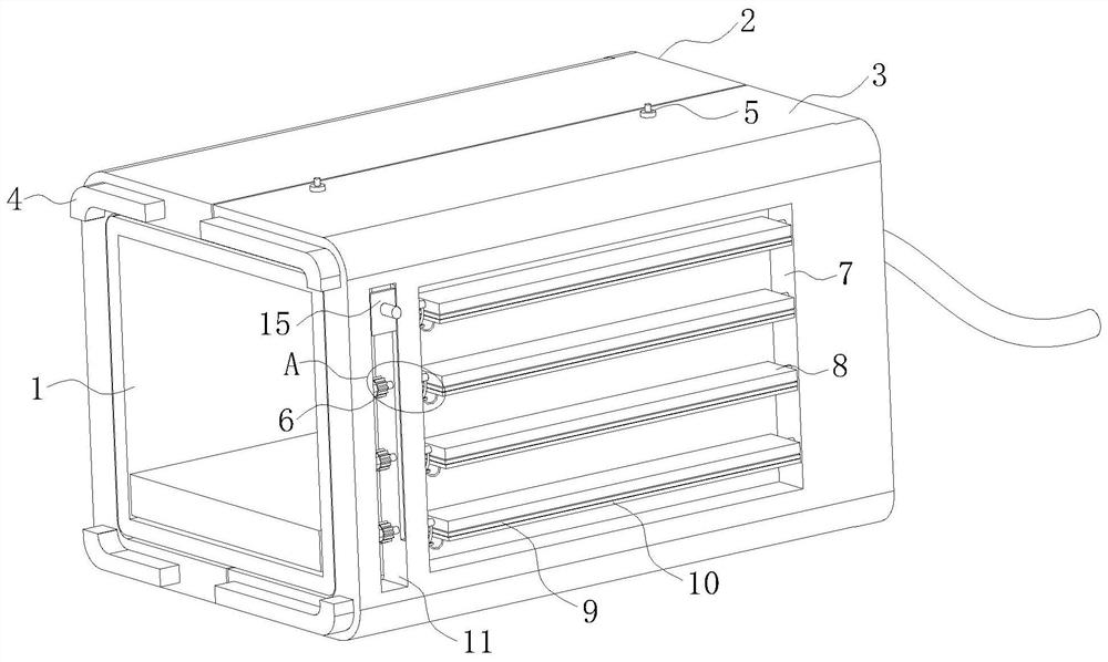
[0036] As an embodiment of the present invention, rubber rollers 23 are evenly arranged on the edge of the part of the rotating rod 12 located in the circular through groove 24; both ends of the rotating shaft of the rubber roller 23 are fixedly connected by springs On the edge of the rotating rod 12; when working, the rubber roller 23 is pressed against the inner wall of the circular through groove 24 by a spring, and then the position of the rotating rod 12 can be fixed to prevent the external force from easily causing the rotating rod 12 to rotate , to avoid changing the position of the heat conduction plate 8 and affecting the effect it actually wants to achieve, and this design makes the position of the rotating rod 12 slightly offset, and then in the process of rotating the heat conduction plate 8 and does not want to achieve When its end face is attached to the outer wall of the drive power supply body 1, there may be a buffer space, which will not cause the heat conduction


PUM


Abstract

The invention belongs to the technical field of LED driving power supplies, and particularly relates to a software-defined LED driving power supply. The software-defined LED driving power supply comprises a driving power supply body, wherein a protective sleeve is arranged on the outer side of the driving power supply body; the protective sleeve comprises a first outer shell and a second outer shell; the first outer shell is provided with a clamping groove in the end face making contact with the second outer shell; and the second outer shell is provided with a clamping strip clamped with the clamping groove on the surface making contact with the first outer shell. According to the invention, opening and closing of the rectangular heat dissipation groove are achieved through rotation of a heat conduction plate, so that the rectangular heat dissipation groove can be opened for heat dissipation in hot weather, the rectangular heat dissipation groove is sealed through the heat conduction plate in cold weather, the external cold air can be prevented from invading the driving power supply body to result in damage of the driving power supply body. According to the design of the invention,the driving power supply body can be prevented from being burnt down due to overheating, and meanwhile, the situation that the working performance of the driving power supply body is reduced and eventhe driving power supply body cannot work normally due to cold invasion is also avoided.

Description


Claims


Application Information

Patent Timeline
Owner 安徽易知谷信息科技有限公司
Why Eureka
Try Eureka