Method and device for detecting unit test stability, electronic equipment and storage medium
A unit testing and testing unit technology, applied in software testing/debugging, error detection/correction, electrical digital data processing, etc., to achieve the effect of improving efficiency
- Summary
- Abstract
- Description
- Claims
- Application Information
AI Technical Summary
Benefits of technology
Problems solved by technology
Method used
Image

Examples
Embodiment 1
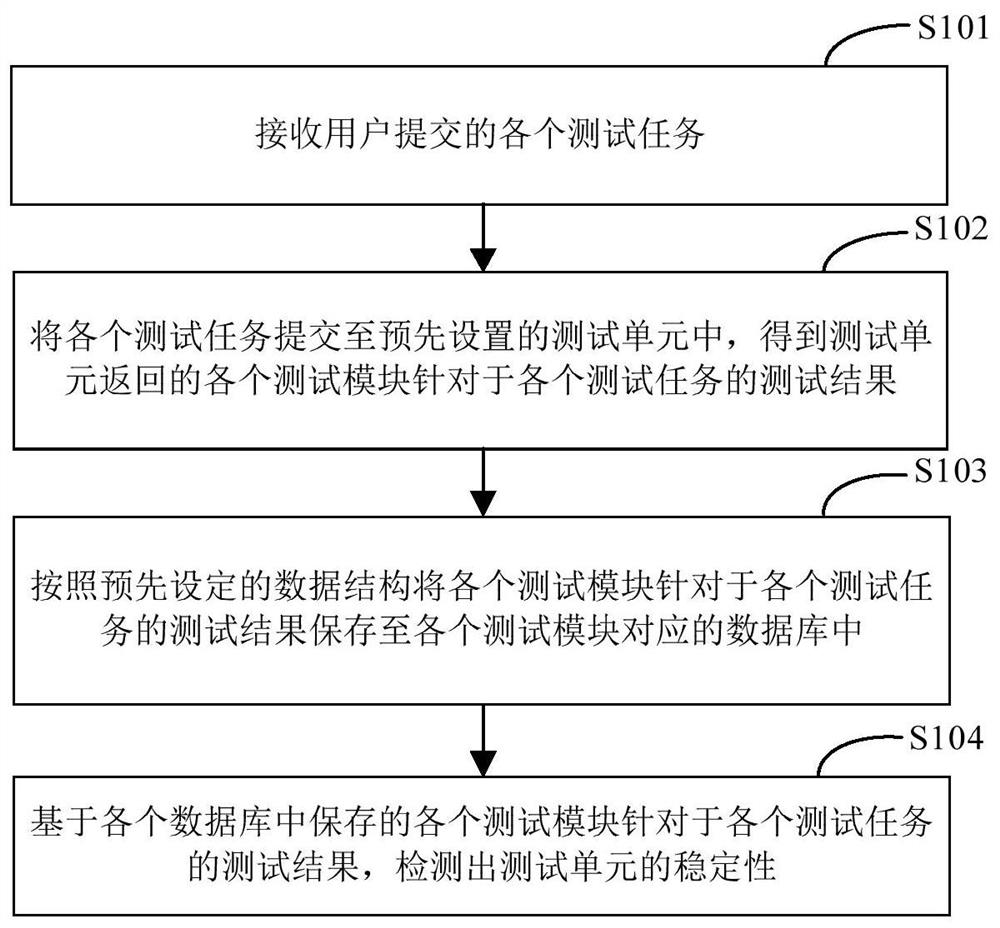
[0030] figure 1 It is the first schematic flow chart of the method for detecting the stability of the unit test provided by the embodiment of the present application. The method can be executed by the device or the electronic device for detecting the stability of the unit test. The device or the electronic device can be implemented by software and / or hardware In this way, the device or electronic device can be integrated into any smart device with network communication function. Such as figure 1 As shown, the method for detecting the stability of a unit test may include the following steps:
[0031] S101. Receive each test task submitted by a user.
[0032] In this step, the electronic device may receive various test tasks submitted by the user. Each test task is used to request the test unit to test a program or code with a specific function.
[0033] S102. Submit each test task to a preset test unit, and obtain the test results of each test module for each test task retur
Embodiment 2
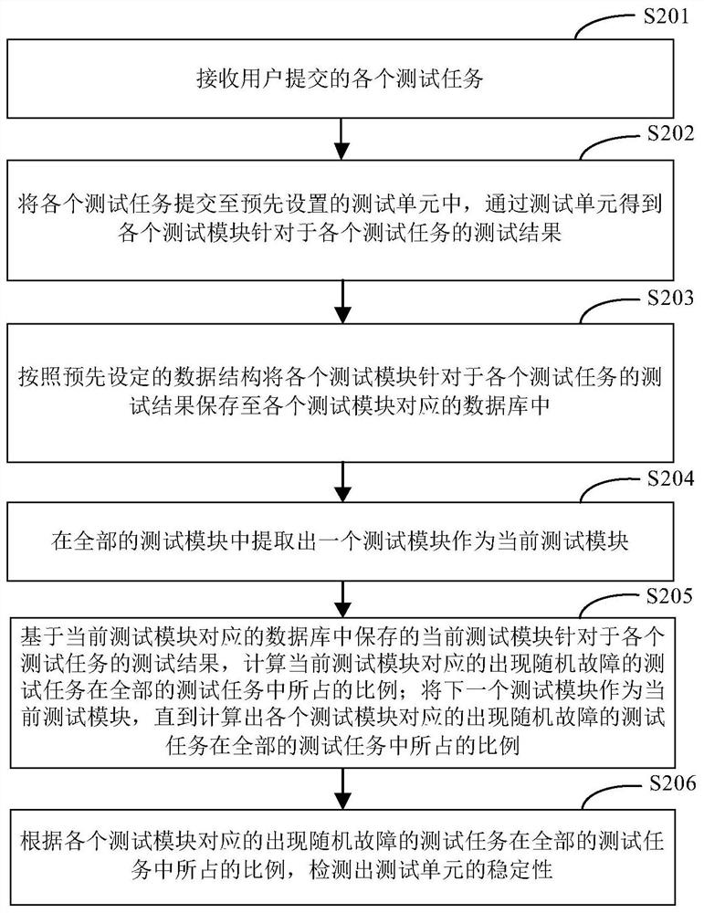
[0041] figure 2 It is the second schematic flowchart of the method for detecting the stability of a unit test provided in the embodiment of the present application. Further optimization and expansion based on the above technical solution, and may be combined with each of the above optional implementation modes. Such as figure 2 As shown, the method for detecting the stability of a unit test may include the following steps:
[0042] S201. Receive each test task submitted by the user.
[0043] S202. Submit each test task to a preset test unit, and obtain test results of each test module for each test task through the test unit.
[0044] S203. Save the test results of each test module for each test task in a database corresponding to each test module according to a preset data structure.
[0045] In this step, the electronic device may save the test results of each test module for each test task in a database corresponding to each test module according to a preset data structu
Embodiment 3
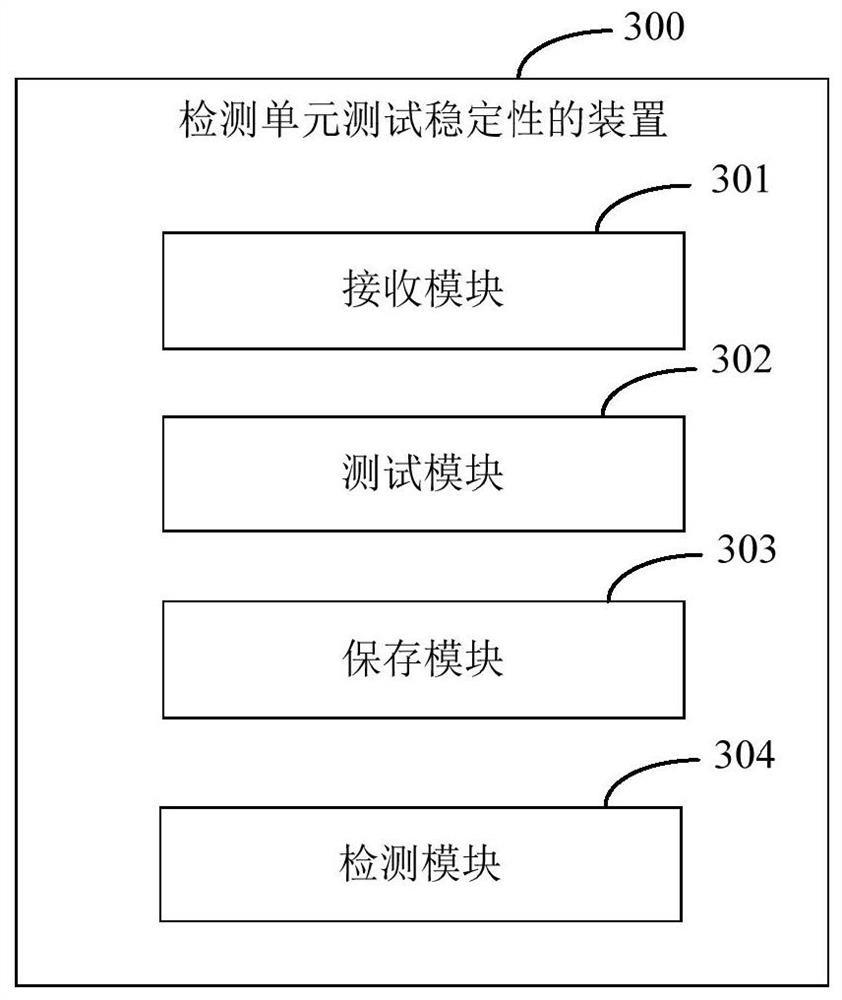
[0057] image 3 It is a schematic structural diagram of a device for detecting unit test stability provided in an embodiment of the present application. Such as image 3 As shown, the device 300 includes: a receiving module 301, a testing module 302, a saving module 303 and a detecting module 304; wherein,
[0058]The receiving module 301 is configured to receive each test task submitted by the user;
[0059] The test module 302 is configured to submit each test task to a preset test unit, and obtain the test results of each test module for each test task through the test unit;
[0060] The saving module 303 is used to save the test results of each test module for each test task in the database corresponding to each test module according to a preset data structure;
[0061] The detection module 304 is configured to detect the stability of the test unit based on the test results of each test module stored in each database for each test task.
[0062] Further, the test results
PUM
 Abstract
Description
Claims
Application Information
 - R&D Engineer
- R&D Manager
- IP Professional
- Industry Leading Data Capabilities
- Powerful AI technology
- Patent DNA Extraction
Browse by: Latest US Patents, China's latest patents, Technical Efficacy Thesaurus, Application Domain, Technology Topic.
© 2024 PatSnap. All rights reserved.Legal|Privacy policy|Modern Slavery Act Transparency Statement|Sitemap