Fireproof transformer with clamping device
A technology for a clamping device and a transformer, applied in the field of transformers, can solve the problems of inconvenient use, poor heat dissipation, and poor internal heat dissipation effect, and achieve the effect of enhanced practicability
- Summary
- Abstract
- Description
- Claims
- Application Information
AI Technical Summary
Problems solved by technology
Method used
Image

Examples
Embodiment 1
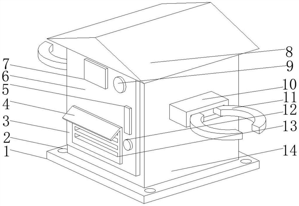
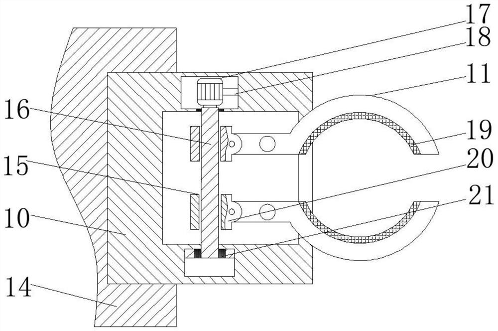
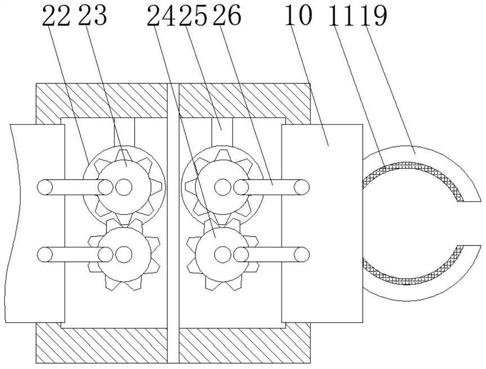
[0031] see Figure 1-4 , a fire-resistant transformer with a clamping device, including a cabinet body 14, expansion plates 10 are provided on both sides of the cabinet body 14, a clamping block 11 is provided inside the expansion plate 10, and one end of the clamping block 11 is flexibly connected There is a slider 20, the inside of the clamping block 11 is fixedly connected with a rubber pad 19, the inside of the slider 20 is provided with a screw hole 15, and the inside of the screw hole 15 is provided with a screw rod 16, and one end of the screw rod 16 is fixedly connected to a No. 1 servo motor 17 One side of No. 1 servo motor 17 is fixedly connected with No. 1 connector 18, bearings 21 are arranged between the two ends of screw rod 16 and telescopic plate 10, No. 2 servo motor 22 is provided at one end of telescopic plate 10, No. 2 servo One side of the motor 22 is fixedly connected with a No. 2 connector 25, the output shaft of the No. 2 servo motor 22 is fixedly connecte
Embodiment 2
[0034] see figure 1 and 4 , the present embodiment is further optimized on the basis of Embodiment 1, specifically, the front of the cabinet 14 is provided with a cabinet door 6, the top of the cabinet 14 is fixedly connected with an upper cover 8, and the bottom of the cabinet 14 An installation base plate 1 is fixedly connected, and an installation hole 2 is provided around the top of the installation base plate 1 .
[0035] Specifically, the front of the cabinet door 6 is provided with a ventilation panel 3 , and the front of the ventilation panel 3 is provided with a ventilation hole 13 .
[0036] Specifically, a stepless speed regulation motor 27 is provided on the back side of the ventilation plate 3 , the output shaft of the stepless speed regulation motor 27 is fixedly connected with a fan blade 29 , and a fan groove 28 is arranged outside the fan blade 29 .
[0037] In this embodiment, when the equipment needs to be ventilated, the stepless speed regulation motor 27 dr
Embodiment 3
[0039] see figure 1 and 4 , the present embodiment is optimized as follows on the basis of Example 1 or Example 2, specifically, the upper end of the ventilation hole 13 is provided with a rain shield 4, and one side of the rain shield 4 is provided with a keyhole 12 and a handle 5.
[0040] Specifically, the key hole 12 is circular, and the handle 5 is rectangular.
[0041] Specifically, the top of the cabinet door 6 is provided with a display screen 7, and one side of the display screen 7 is provided with a warning light 9, the display screen 7 is rectangular, and the warning light 9 is circular.
[0042] Specifically, an induction controller 30 is provided inside the cabinet body 14 , and there are multiple induction controllers 30 , and the plurality of induction controllers 30 are evenly distributed inside the cabinet body 14 .
[0043] In this embodiment, by setting the upper cover 8 into a triangle, the rainwater can flow down quickly when it rains, and the setting of th
PUM
 Abstract
Description
Claims
Application Information
 - R&D Engineer
- R&D Manager
- IP Professional
- Industry Leading Data Capabilities
- Powerful AI technology
- Patent DNA Extraction
Browse by: Latest US Patents, China's latest patents, Technical Efficacy Thesaurus, Application Domain, Technology Topic.
© 2024 PatSnap. All rights reserved.Legal|Privacy policy|Modern Slavery Act Transparency Statement|Sitemap