Arranging and discharging device for plastic salt bottles

The technology of a discharging device and a salt shaker is applied in the field of sorting and discharging devices for plastic salt shakers, which can solve the problems of pollution of plastic salt shakers, low work efficiency, inability to use, etc., and achieves high work efficiency, convenient packaging operation, and simple operation. handy effect

Active Publication Date: 2020-12-08
安徽强旺生物工程有限公司
View PDF14 Cites 0 Cited by
  • Summary
  • Abstract
  • Description
  • Claims
  • Application Information

AI Technical Summary

Problems solved by technology

[0003] Plastic salt bottles need to be sorted and discharged after production to facilitate subsequent packaging operations for plastic salt bottles. Enterprises generally use manual sorting and disch

Method used


Image

  • Arranging and discharging device for plastic salt bottles
  • Arranging and discharging device for plastic salt bottles
  • Arranging and discharging device for plastic salt bottles

Examples


Example Embodiment

[0021] The technical solutions in the embodiments of the present invention will be clearly and completely described below with reference to the drawings in the embodiments of the present invention. Obviously, the described embodiments are only part of the embodiments of the present invention, but not all of them. Based on the embodiment of the present invention, all other embodiments obtained by ordinary technicians in the field without creative labor are within the scope of the present invention.

[0022] In the description of the present invention, it should be noted that the directions or positional relationships indicated by the terms "vertical", "upper", "lower" and "horizontal" are based on the directions or positional relationships shown in the drawings, only for the convenience of describing the present invention and simplifying the description, instead of indicating or implying that the referred devices or elements must have a specific direction, be constructed and operated


PUM


Abstract

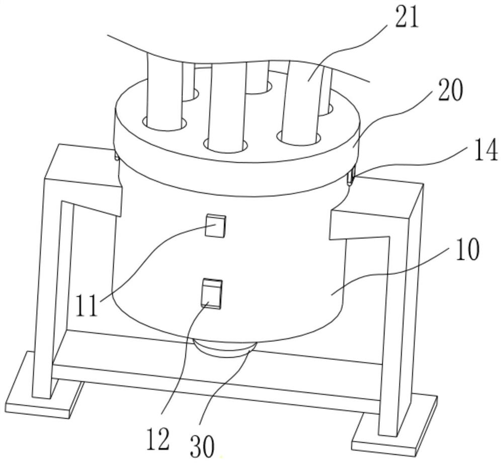
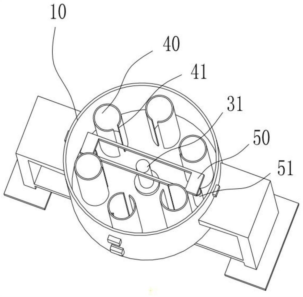
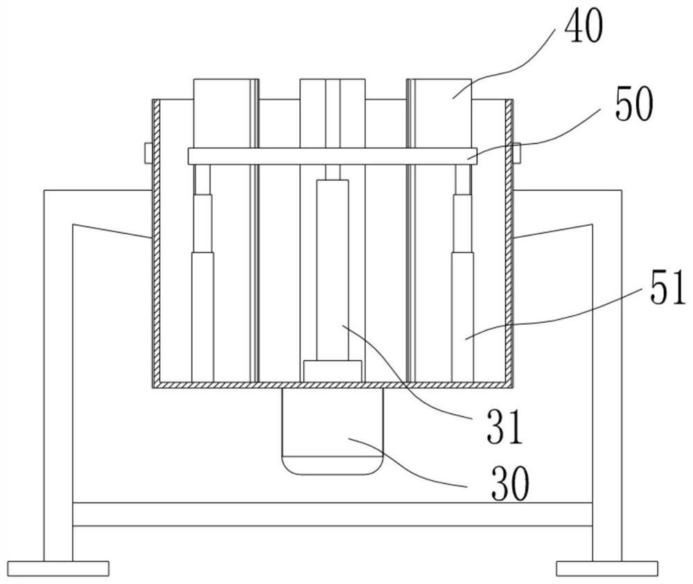
The invention discloses an arranging and discharging device for plastic salt bottles. The arranging and discharging device comprises a box body, a discharging mechanism and a driving mechanism. A plurality of sets of material collecting cylinders are arranged in the box body around the central axis. A protective cover is installed at the top end of the box body. A plurality of sets of feeding ports are formed in the protective cover. The feeding ports correspond to the material collecting cylinders one to one. The discharging mechanism comprises push plates, a bottom plate and a movable rod. The push plates are movably arranged at the bottoms of the material collecting cylinders. Blanking grooves are arranged at the upper ends of the push plates. The bottom plate is arranged at the bottomof the box body and connected with the push plates through connecting rods. The movable rod is arranged in the box body. The movable rod and the box body share the same central axis. The movable rod is provided with a cavity. The lower end of the movable rod is connected with the bottom plate, and a handle is installed at the upper end of the movable rod. The driving mechanism comprises a hydraulic cylinder and a push rod. The hydraulic cylinder is arranged at the bottom of the box body. The push rod is arranged in the cavity of the movable rod, and the lower end of the push rod is connected with the output end of the hydraulic cylinder.

Description


Claims


Application Information

Patent Timeline
Owner 安徽强旺生物工程有限公司
Why Eureka
Try Eureka